Discharge lamp

Inactive Publication Date: 2006-08-03
USHIO DENKI KK
View PDF12 Cites 7 Cited by
  • Summary
  • Abstract
  • Description
  • Claims
  • Application Information

AI Technical Summary

Benefits of technology

[0009] The invention was devised to eliminate the aforementioned disadvantages. Thus, a primary object of the present invention is to devise a discharge lamp of the short arc type in which the temperature rise of the sealing components can be suppressed and in which the sealing components are not damaged even if, by m

Problems solved by technology

This results in the f

Method used


Image

  • Discharge lamp
  • Discharge lamp
  • Discharge lamp

Examples


Embodiment Construction

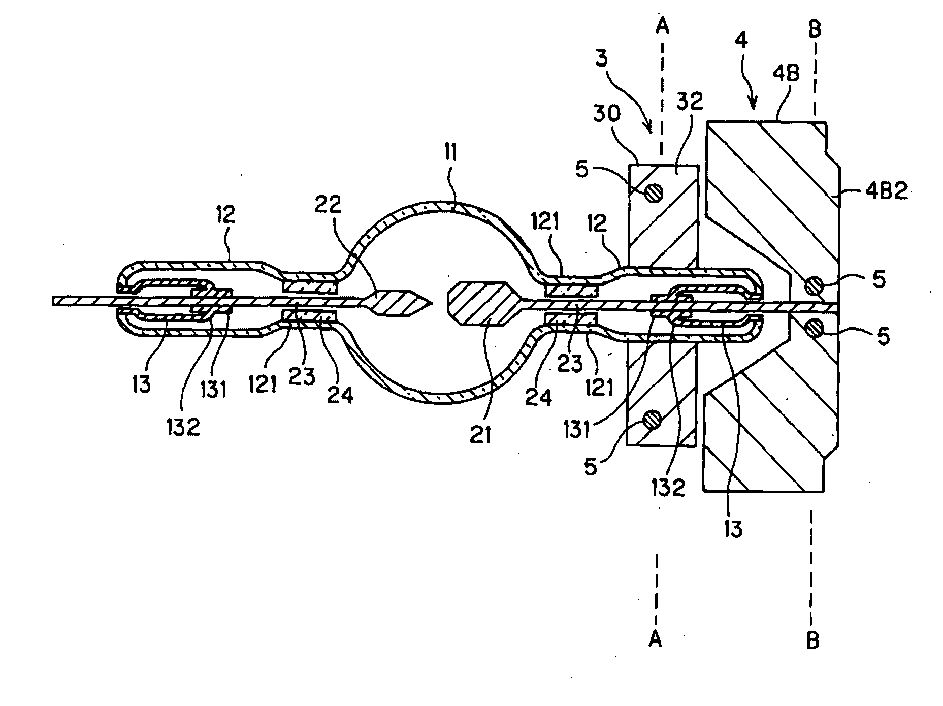
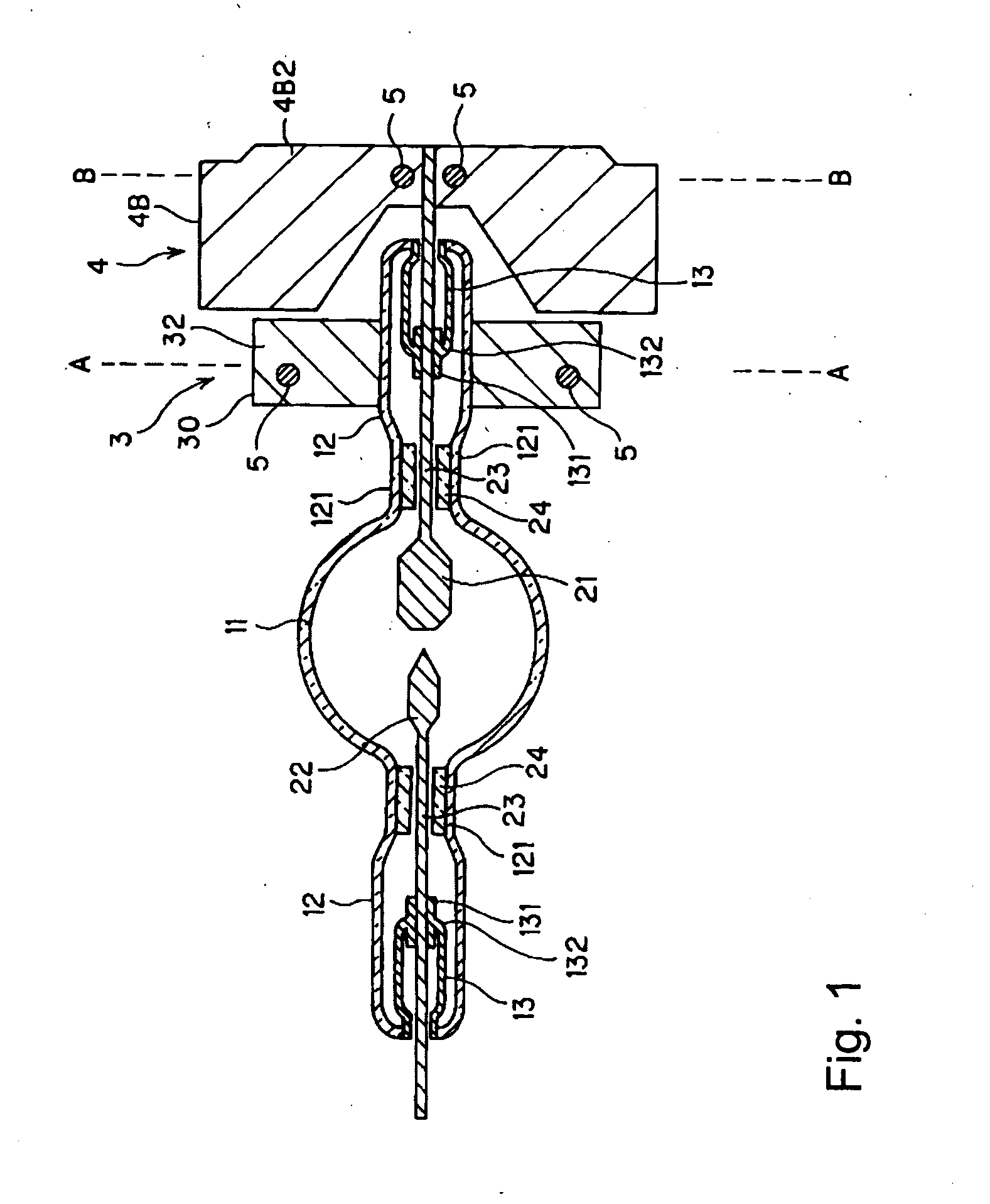
[0026] A discharge lamp of the short arc type in accordance with the invention is described below using FIG. 1. An essentially spherical arc tube 11 of silica glass is integrally and continuously connected on each of opposite sides to a respective sealing part 12. The arc tube 11 is filled with xenon gas, and a pair of electrodes, i.e., an anode 21 and a cathode 22, are located in opposed relationship to each other. The anode 21 and cathode 22 are each joined to the tip of a tungsten lead pin 23.

[0027] Silica glass cylindrical retaining bodies 24are located within the sealing parts 12 at their ends that are near the respective side of the arc tube 11. Lead pins 23, which support either the anode 21 or the cathode 22, are inserted into an opening which has been formed in the middle of the respective cylindrical retaining body 24. Pinched parts 121 are formed, and thus, the electrodes are supported by heating and by reducing the diameter of the sealing parts 12 in which the cylindric...


PUM


Abstract

A discharge lamp of the short arc type in which the temperature rise of the sealing components of graded glass within the sealing part can be suppressed and in which the sealing components are not damaged is achieved, in a such lamp that has sealing parts which border the arc tube on opposite sides, and lead pins which each support a electrode in the arc tube, and are sealed within the respective sealing part by graded glass, by a component for cooling the sealing part being provided on the outside of at least one of the sealing parts, and by a component for cooling the lead pin being provided on at least one of the lead pins, in the area in which it projects outward from the graded glass within the sealing part which is provided with the component for cooling the sealing part.

Description

BACKGROUND OF THE INVENTION [0001] 1. Field of the Invention [0002] The invention relates to a discharge lamp of the short arc type. The invention relates, for example, to a discharge lamp of the short arc type which is suited for a light source of a projector device or the like, in which light modulation elements are irradiated with light and in which images are projected by the reflected light. [0003] 2. Description of the Related Art [0004] A conventional discharge lamp of the short arc type with an arc tube 11 filled with xenon is shown in FIG. 7 and is known for use as a light source of a projection device, such as a projector or the like. In this lamp, as a result of increasing the radiance, the internal pressure of the arc tube 11 is very high during operation, so that a construction is required such that, even at a high internal pressure, the sealing parts 12 of the lamp are not damaged. Furthermore, it is necessary for the lead pins 23 which support electrodes 21, 22 to pro...

Claims


Application Information

Patent Timeline
IPC IPC(8): H01J7/24
CPCH01J5/48H01J61/523H01J61/86
Inventor MORIMOTO, SHUNICHIINAOKA, NORIHIROFUJINA, KYOSUKE
Owner USHIO DENKI KK
Why Eureka
Try Eureka