Compensation of simple fiber optic faraday effect sensors

Active Publication Date: 2006-08-03
LANDIS & GYR OY
View PDF5 Cites 66 Cited by
  • Summary
  • Abstract
  • Description
  • Claims
  • Application Information

AI Technical Summary

Benefits of technology

[0012] The communication unit further provides the opportunity of performing a remote configuration of the system, giving an operator the possibility to configure the system, e.g. defining levels for peak currents, voltage drop out levels, time out values and alerting options.
[0179] To ensure a short-circuit indication in these cases, the system automatically switches to non-directional indication if one or more LV voltages are below a set limit for more than aa set period. In this way, non-directional short-circuit indications are still available, enabling faster fault location.

Problems solved by technology

The determination of the current to be measured is subject to a number of sources of error.
Any system based on optics or electrical circuits are sensitive to noise and other signal degradations, such as optical noise or interference from electromagnetic sources.
A system comprising a light source, a light detection unit and an optical conduit such as an optical fiber may suffer loss of sensitivity due to optical dampening caused by defects in material used to form an optical conduit or device such as lenses or optical fibers.
Light sources and light detection circuitry may be exposed to electrical noise or interference from magnetic fields from nearby inductors or systems alternatively noise caused by fluctuations in the power supply.
Furthermore, all electrical components and light sources and light detection elements suffer degradation over time.

Method used


Image

  • Compensation of simple fiber optic faraday effect sensors
  • Compensation of simple fiber optic faraday effect sensors
  • Compensation of simple fiber optic faraday effect sensors

Examples


Embodiment Construction

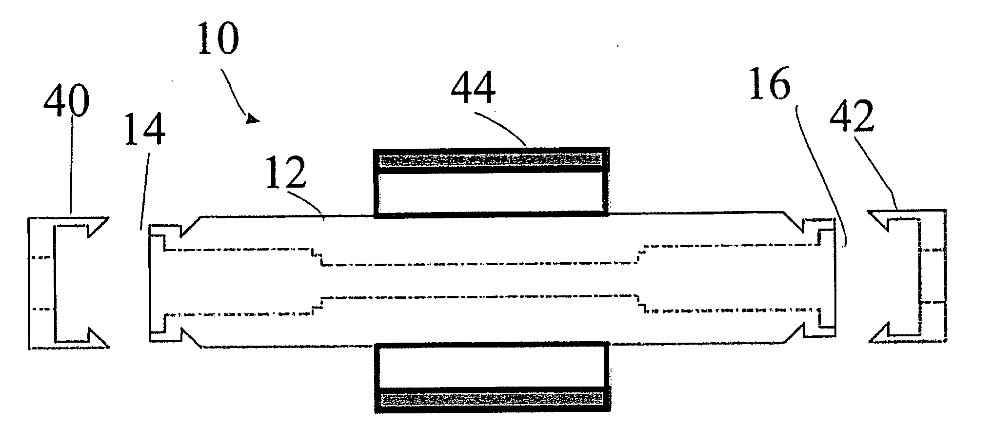
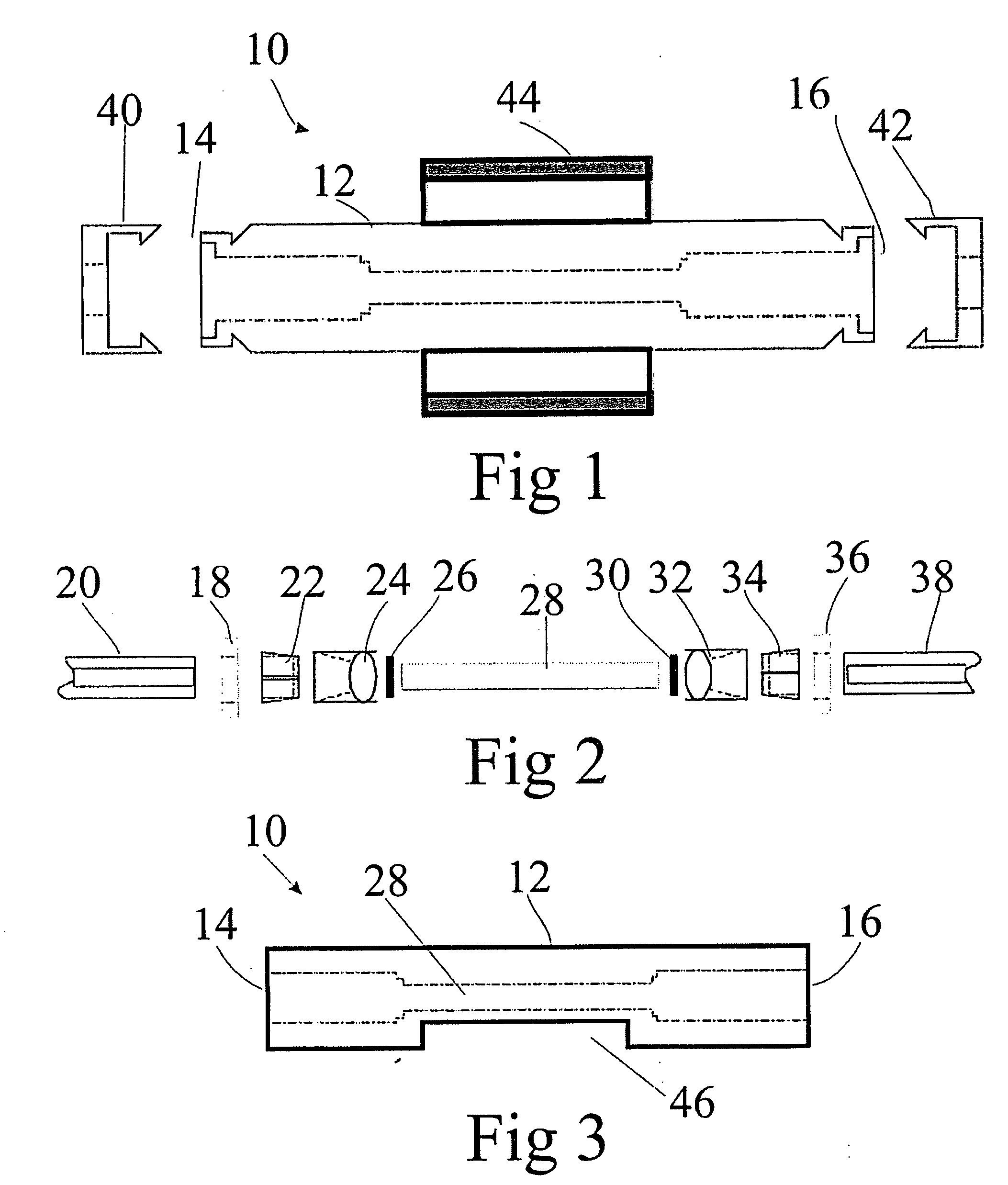
[0311]FIG. 1 is a schematic cross sectional view of a Faraday optical current sensor 10, and FIG. 2 is a zoomed schematic cross sectional view of the Faraday optical current sensor 10 of FIG. 1. The Faraday optical current sensor 10 comprises an oblong housing 12 defining a first and an opposite second end; designated 14 and 16 respectively. At the first end 14 of the housing 12 a first sealing 18 is mounted, the first sealing 18 having an aperture for receiving a first optical fiber 20. A first fiber fixture 22 mounted in the housing 12. The first fiber fixture 22 having a aperture for receiving an optical fiber 20. An optical lens 24 having a receiving section for receiving the optical fiber 20 and the fiber fixture 22. A first polarization filter 26 mounted in optical continuation with the optical lens 24. A glass rod 28 in optical continuation with the first polarization filter 26. At the opposite end of the glass rod 28 a second polarization filter 30 is mounted in optical cont...


PUM


Abstract

A monitoring system for detecting earth faults in an electrical power supply grid providing a power signal includes a plurality of monitoring devices, each of the monitoring devices including a detector for detecting the level of harmonics in the power signal, wherein the level of harmonics is detected in a specific frequency range. Each of the monitoring devices further includes a memory for storing a harmonics reference value, a processor for comparing the detected level of harmonics with the reference level, and a communication device for transmitting an alarm if the detected level of harmonics is above the reference level for a specific period of time. Each of the detectors includes an optical sensor for detecting the harmonics by use of the Faraday effect.

Description

CROSS-REFERENCE TO RELATED APPLICATION [0001] This application claims the benefit, under 35 U.S.C.§119(e), of co-pending U.S. Provisional Application No. 60 / 629,213, filed Nov. 18, 2004, the disclosure of which is incorporated herein by reference.BACKGROUND OF THE INVENTION [0002] The invention relates to a Faraday optical current sensor with polarimetric detection. The present invention further relates to a method of calibrating a current sensor system including a Faraday optical current sensor. [0003] The power industry has a need for monitoring transformer stations for power surges and measurement of large current pulses. For these purposes, a Faraday Effect current sensor has several advantages. A Faraday Effect current sensor may be constructed from dielectric materials, which is of grave importance when measuring at high currents in the presence of substantial electric magnetic interference. Faraday Effect current sensors may employ a coil of an optical fiber or a number of op...

Claims


Application Information

Patent Timeline
IPC IPC(8): G01R31/00
CPCG01R15/246G01R33/0322G01R31/025G01R19/2513H04W4/14G01R31/52G01R1/00H04L67/12
Inventor BJORN, LARS N.
Owner LANDIS & GYR OY
Why Eureka
Try Eureka