
Closed loop power control with high dynamic range

Active Publication Date: 2006-08-03
APPLE INC
View PDF7 Cites 57 Cited by
  • Summary
  • Abstract
  • Description
  • Claims
  • Application Information

AI Technical Summary

Problems solved by technology

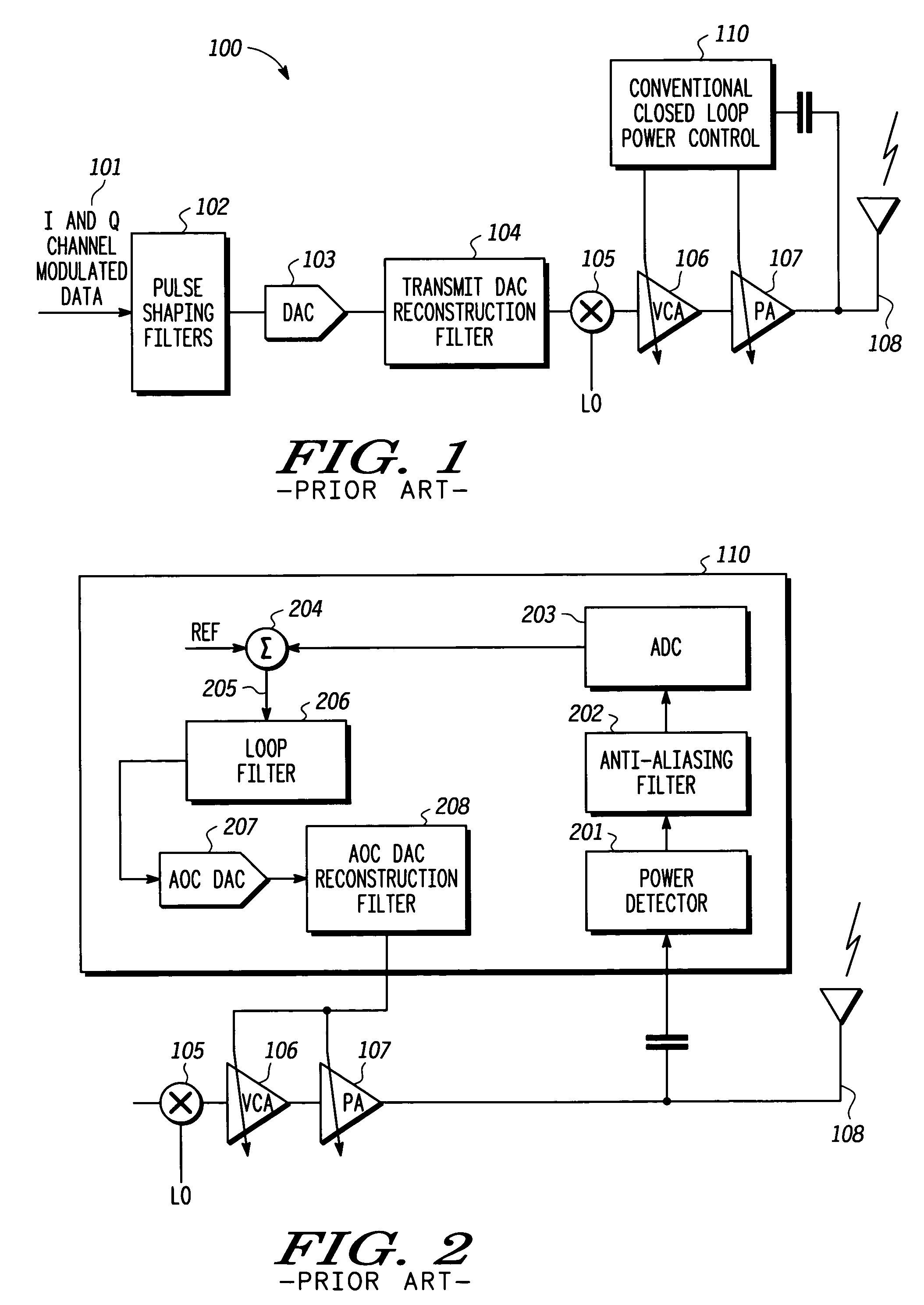
As a result, the closed loop power control range is limited leading to performance degradation such as loss of power accuracy, failure to meet Power versus Time masks, unacceptable transient ACP, and the like.
Further, PA efficiency can be reduced due to current drain resulting from the loss of load switching capability in the PA across the lost converter range.
Further limitations occur during transmit power transitions associated with switching from a power level associated with, for example, a first slot, to a power level associated with a second slot.
The transitions require a ramp-up or ramp-down depending on the next power level and poor power control during such intervals can cause disturbances in the loop bandwidth ultimately increasing convergence or settling time for new gain levels.
Transmit power transients and the like during ramp or transition intervals may further cause a transmitter to exceed power masks and result in instability at least for a period of time until a post transition gain level settles.

Method used


Image

  • Closed loop power control with high dynamic range
  • Closed loop power control with high dynamic range
  • Closed loop power control with high dynamic range

Examples


Embodiment Construction

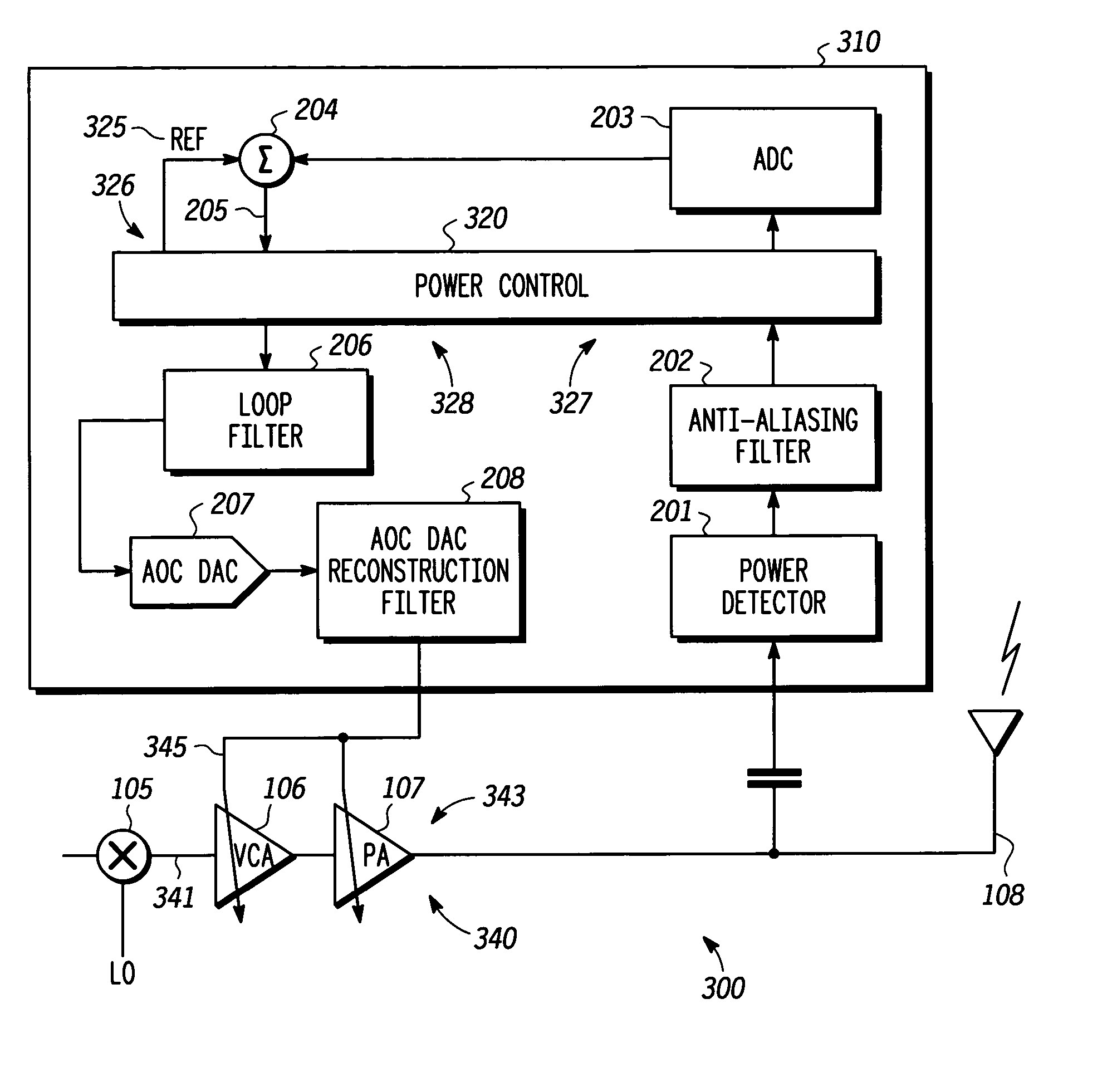
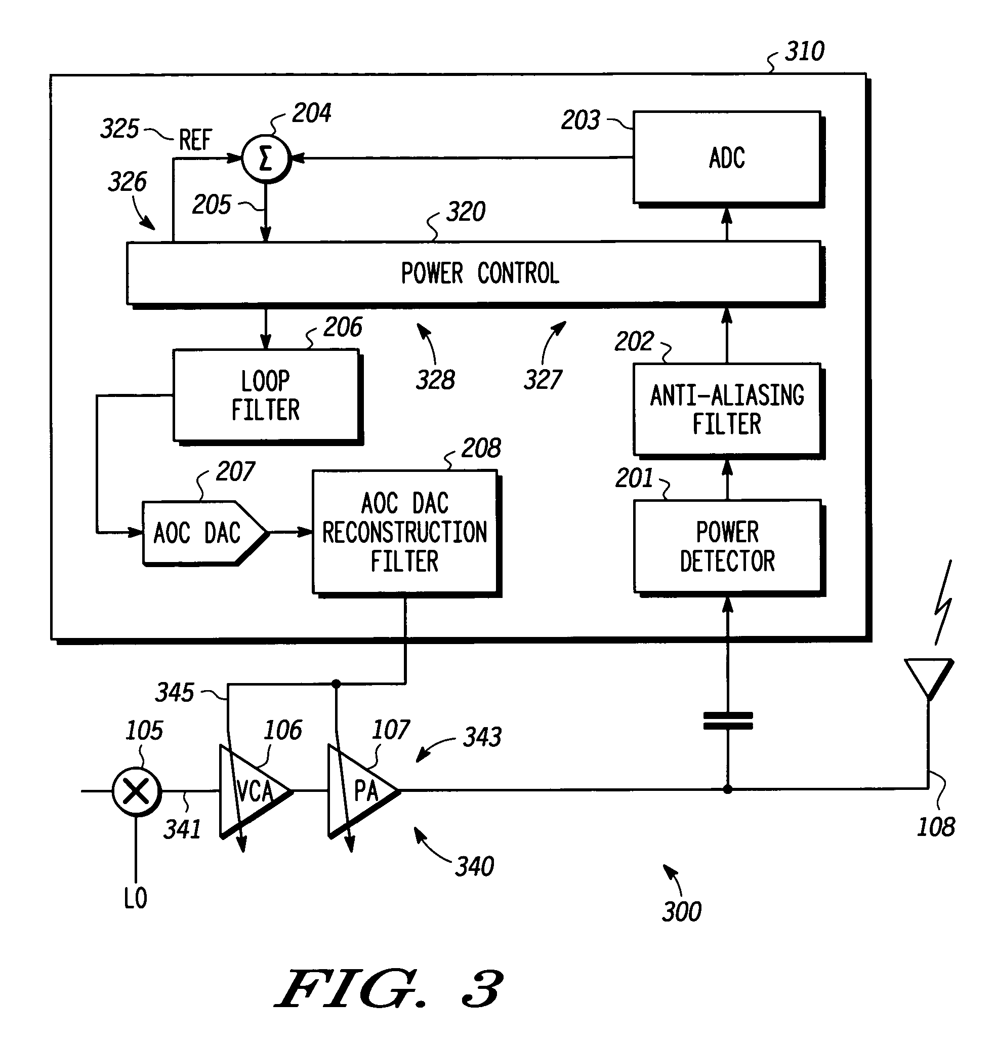
[0014] In overview, the present invention relates to transmit power control in wireless communication systems for facilitating communications between devices or units, often referred to as communication units, such as cellular telephones or two-way radio handsets and the like. The present invention can be implemented in a mixed signal power control system architecture providing a detect path dynamic range much greater than that of, for example, a feedback A / D converter to resolve disadvantages present in many conventional systems. The increase in the detect path A / D range is achieved automatically by the mixed signal architecture without requiring special factory phasing steps or special software setup by an external host processor or the like thereby resulting in reduced production costs. Further advantages associated with power control in accordance with various exemplary embodiments include the elimination of software setup timing issues occurring prior to each power transition—a...


PUM


Abstract

A method (500) and apparatus (300, 400, 601) facilitate closed loop transmit power control in a power control loop at and during a transition from one transmit power level to another transmit power level in a transmitter. The apparatus includes a reference path (326) configured to provide a reference signal (325) and a gain compensation signal (417), a detect path (327) configured to process, in accordance with the gain compensation signal, a detected signal corresponding to a power level to provide a gain compensated detected signal; and a power control path (328) configured to generate a power control value in accordance with the reference signal, the gain compensated detected signal, and a loop compensation factor associated with the gain compensation signal where the power control value is suitable for setting the power level for the transmission.

Description

FIELD OF THE INVENTION [0001] The present invention relates in general to wireless communication systems, and more specifically to a method and apparatus for performing power control in a wireless transmitter. BACKGROUND OF THE INVENTION [0002] Power control of the transmission signal is a critical performance and efficiency aspect in wireless communication systems and associated networks such as Global System Mobile (GSM), Enhanced Data rate for GSM Evolution (EDGE), Wideband Code Division Multiple Access (WCDMA), High Speed Downlink Packet Access (HSDPA) systems and the like. In order to meet rigid specifications for transmission in such environments including transmission power vs. time masks, frequency domain transmission power emission masks, and the like, particularly over a variety of temperature ranges, power supply voltage ranges, and the like, precise transmit power control must be achieved, most often with closed loop power control. [0003] A target power level associated ...

Claims


Application Information

Patent Timeline
IPC IPC(8): H03G3/10H04B1/707H04B1/713
CPCH03G3/3047H03G3/10
Inventor RAHMAN, MAHIBURIVONNET, JORGEPREMAKANTHAN, PRAVINKUMAR
Owner APPLE INC
Learn More