Object detection device

a technology of object detection and detection area, which is applied in the direction of antenna details, instruments, antennas, etc., can solve the problems of complex and time-consuming procedures for adjusting the detection area, increasing the size of the object detection device, so as to achieve easy adjustment and easy and quick

Active Publication Date: 2006-08-03
OPTEX CO LTD
View PDF5 Cites 2 Cited by
  • Summary
  • Abstract
  • Description
  • Claims
  • Application Information

AI Technical Summary

Benefits of technology

[0008] The present invention has been devised to substantially eliminate the foregoing problems and inconveniences and is intended to provide an object detecting device having a capability of sufficiently adjusting the detection area to suit to the environment in which it is installed.
[0011] According to the present invention, adjustment of the detection area to one of the different shapes can be accomplished by selecting one of the adjusting covers used to cover the antenna. Accordingly, when one of the adjusting covers, each used to cover the antenna, and which are provided for adjusting the detection area to the different shapes one at a time, is selected to cover the antenna, the detection area of a desired or required shape that is sufficiently adjusted can easily be defined as necessary. Also, since the antenna itself is protected by the selected adjusting cover, there is no possibility that the orientation of the antenna may be displaced purposelessly and / or the antenna may be damaged and, therefore, the function of the antenna may not be lowered.
[0013] According to this preferred feature, a relatively wide detection area (a wide area) can easily be set up. Moreover, generation of side lobes tending to occur at lateral portions of a primary beam component of the radiation beam of the detection wave emitted from the antenna can be forcibly suppressed by the presence of the cutouts. Accordingly, without the output of the primary beam being lowered, unnecessary detection areas, which ought not to be formed other than the detection area defined by the primary beam component, will not be formed. Thus, since no output of the primary beam component is lowered, the detection accuracy in the detection area is excellent and, accordingly, since no unnecessary detection area is formed, even when the object detecting device is used as a detection sensor for selectively opening or closing, for example, an automatic door assembly, the presence of a human body and / or an object within the unnecessary detection areas will never be detected, thereby eliminating an erroneous operation of the automatic door assembly, in which the automatic door is selectively opened or closed when it ought not to be opened or closed.
[0015] According to this preferred feature, the presence of the convex lens portion allows the directionality of the detection wave, then passing through the convex lens portion, to be narrowed and, therefore, the detection area in the form of a spot (a spot area) having a relatively small depth can also be formed. This leads to the detection area that can be changed considerably.
[0017] According to this preferred feature, since the antenna and the adjusting cover can be fixed in position through the retaining member, turn of the adjusting cover is accompanied by rotation of the antenna to thereby change the shape of the detection area. Accordingly, where the adjusting cover having the cutouts defined therein is employed, turn of the antenna and the adjusting cover through 90° can result in the detection area to be oriented vertically so as to define the narrow area or transversely so as to define the wide area. Thus, selection of one of the wide area and the narrow area can be accomplished by changing the orientation of the single antenna, with no need to employ dedicated antenna to define the respective required detection areas, resulting in reduction in number of the component parts used and simplification of the structure. Also, by replacing the adjusting cover with an adjusting cover having the convex lens portion, the detection area can easily be adjusted to the spot area.
[0019] According to this preferred feature, turn of the first holder about the first axis can result in adjustment of the detection area in leftward and rightward directions. On the other hand, turn of the second holder about the second axis can result in adjustment of the detection area in forward and rearward directions. Also, turn of the antenna module about the third axis can result in change of the orientation of the antenna with the detection area selected to, for example, one of the wide area and the narrow area. Thus, since the detection area can easily be adjusted in any one of three axes, the installing operation at the site of installation of the object detecting device can easily and quickly be performed.

Problems solved by technology

However, since the horn antenna unit including the horn antenna itself and peripheral parts represents a shape generally similar to the shape of a trumpet and is therefore bulky in size, the use of the horn antenna tends to result in increase in size of the object detecting device and, therefore, the handling of the object detecting device as a whole during the installation thereof tends to be complicated and time-consuming.
Such procedures for adjusting the detection area are indeed complicated and time-consuming.
However, even in the object detecting device utilizing the rotatable dielectric lens discussed above, since only one lens is turned to accomplish the adjustment of the detection area, the width to which the detection area can be adjusted is limited and it may often occur that no sufficient adjustment can be achieved.
The presence of those side lobes means that some of the output of the primary beam component is lost to the side lobes, accompanied by reduction of the output of the primary beam to such an extent that unnecessary detection areas, which ought not to be formed, tend to be formed simultaneously with formation of the detection area defined by the primary beam.
If those unnecessary detection areas are formed in the manner described above, and where the object detecting device is employed as a sensor for selectively detecting opening or closure of an automatic door, the object detecting device will detect a human body or any other object present within any of the unnecessary detection areas, posing the possibility that the automatic door will unnecessarily be closed or opened even though the automatic door ought not to be opened or closed.
Therefore, the prior art is insufficient in that a variety of detection areas to cope with a variety of environments for installation of the object detection device cannot be available.

Method used


Image

  • Object detection device
  • Object detection device
  • Object detection device

Examples


Embodiment Construction

[0032] Hereinafter a preferred embodiment of the present invention will be described in detail with reference to the accompanying drawings.

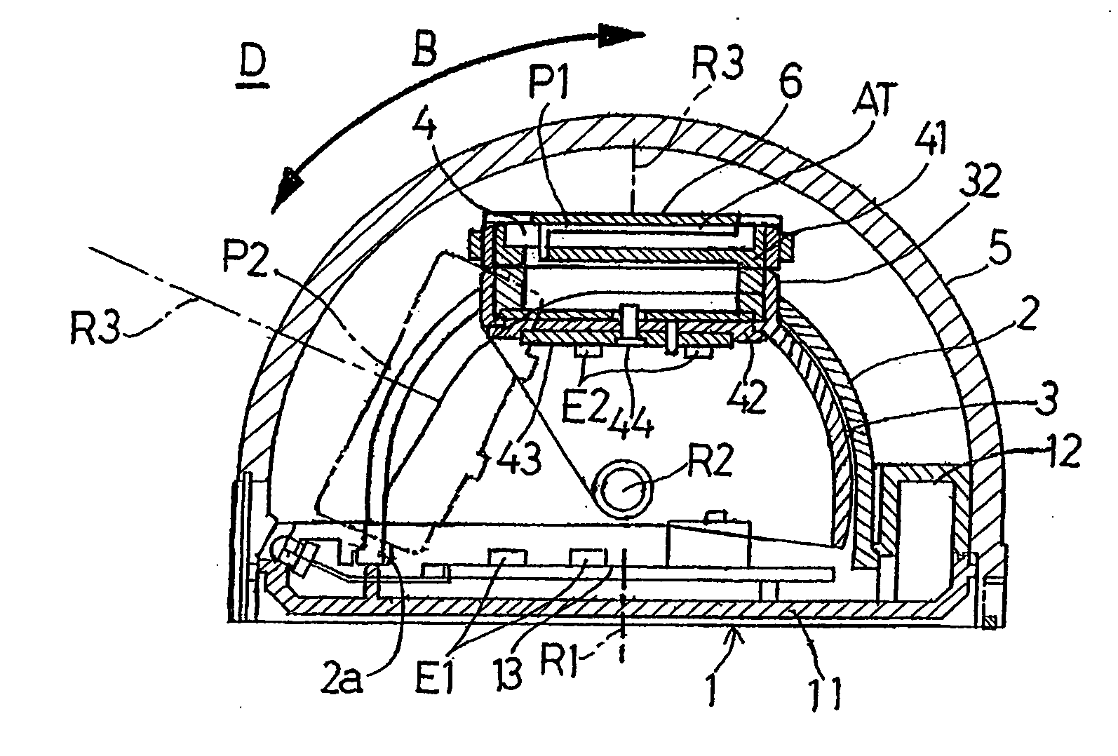
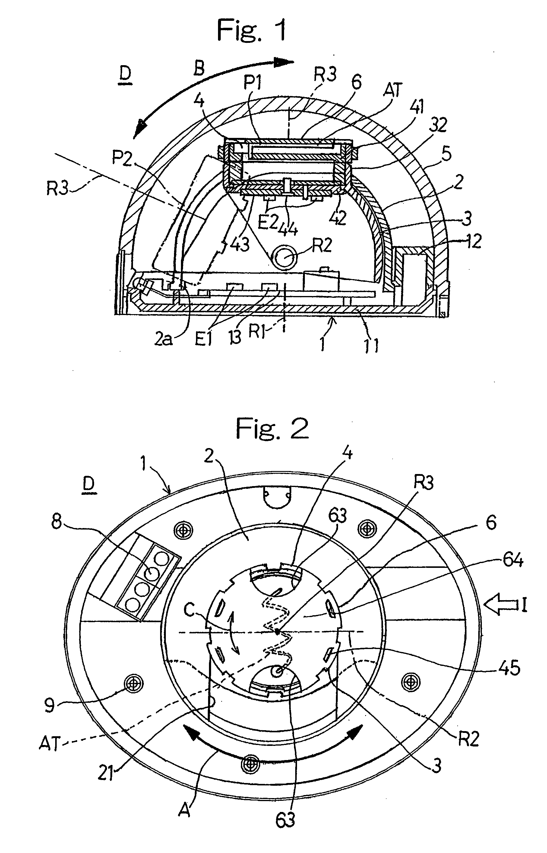
[0033]FIG. 1 illustrates in a transverse sectional representation, an object detecting device according to the preferred embodiment of the present invention as viewed in a direction shown by the arrow I in FIG. 2, while FIG. 2 illustrates a front elevational view of the object detecting device.

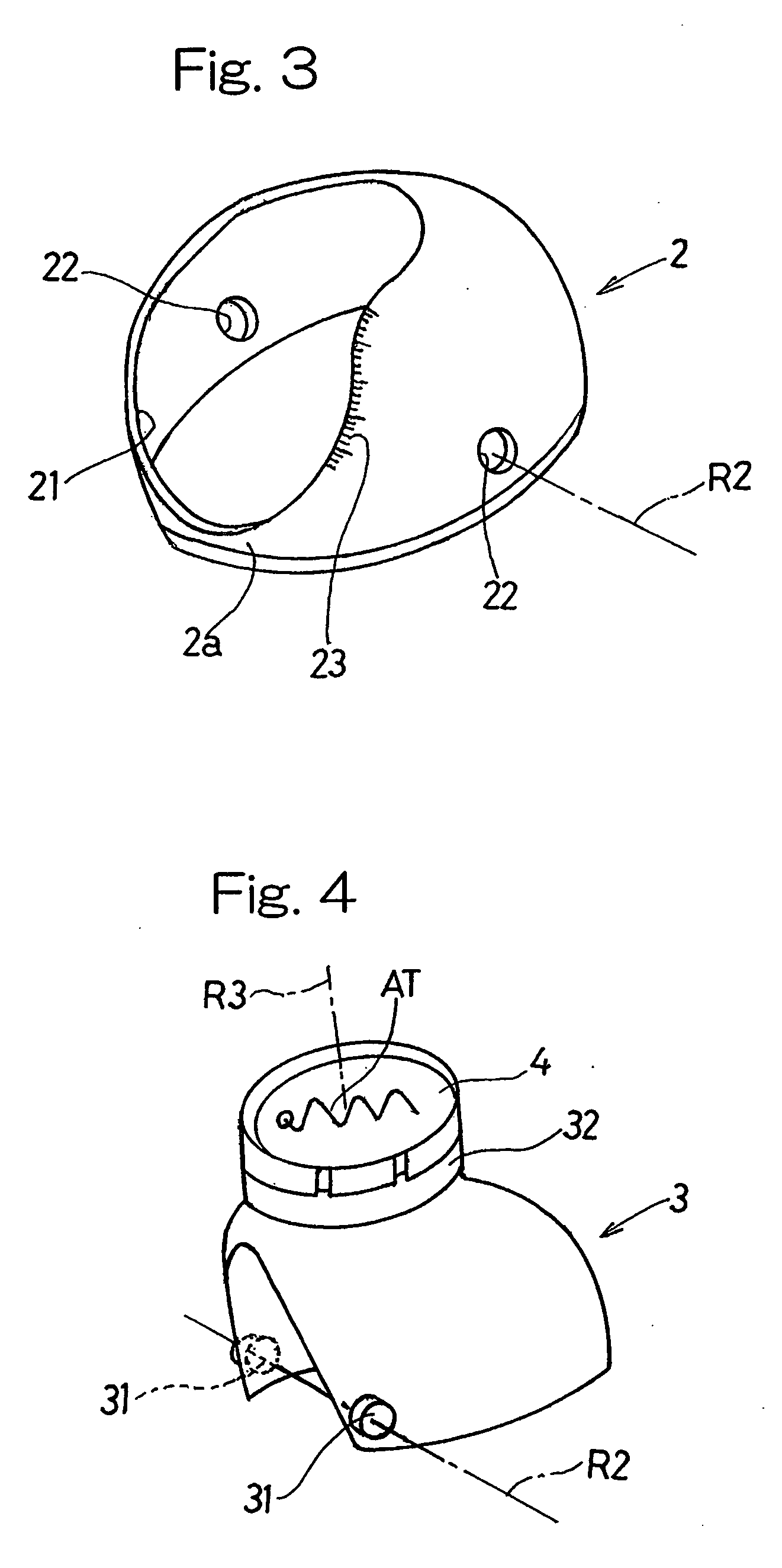
[0034] Referring particularly to FIG. 1, the object detecting device generally identified by D and designed in accordance with the present invention includes a support base 1, a first holder 2 (best shown in FIG. 3) supported above the support base 1 for rotation about a first axis R1 lying perpendicular to a bottom surface of the support base 1, a second holder 3 (best shown in FIG. 4) supported under the first holder 2 for rotation about a second axis R2 lying perpendicular to the first axis R1, and an antenna module 4 for holding an antenna AT for tran...


PUM


Abstract

To provide an object detecting device having a capability of sufficiently adjusting the detection areas to suit to the environment in which it is installed, the object detecting device includes an antenna AT for emitting a detecting beam to the detection areas and receiving a portion of the detecting beam which has been reflected from the detection areas, and adjusting covers 6 and 7 covering a front portion of the antenna AT and operable to adjust respective figurations of the detection areas. The adjusting covers 6 and 7 are selectively fitted one at a time to the front portion of the antenna AT for defining a different figuration of the detection areas. When one of the adjusting covers, that is, the cover 6 that is formed with a pair of cutouts 63 and 63 for suppressing the side lobe of the detecting beam is selectively used, the detection areas can be defined having no unnecessary detection areas.

Description

FIELD OF THE INVENTION [0001] The present invention generally relates to an object detecting device of a kind utilizing microwaves generally employed in association with an automatic door system or for security monitoring purpose and, more particularly, to the object detecting device in which the detection area, from which an object such as, for example, a human body is to be detected, can be properly adjusted in dependence on the environment for installation of the object detecting device. BACKGROUND ART [0002] The object detecting device for an automatic door system or for security monitoring purpose is generally so designed that while a detection wave in the form of a microwave is emitted towards a detection area from which the presence or absence of an object such as, for example, one or more human bodies is desired to be detected, the object can be detected in terms of a change in frequency brought about by the Doppler effect when a portion of the detection wave reflected from ...

Claims


Application Information

Patent Timeline
Patent Type & Authority Applications(United States)
IPC IPC(8): G08B13/00G01V3/12
CPCG01V3/12A61P31/04
Inventor IMANISHI, OSAMUKURATA, MATAICHI
Owner OPTEX CO LTD
Why Eureka
Try Eureka