Projector

a projector and projector body technology, applied in the field of projectors, can solve the problems of long time for determining the in-focus position, short focus adjustment time, and high time consumption of focus adjustment, and achieve the effect of simple structure and easy automatic adjustment control

Active Publication Date: 2006-08-03
SEIKO EPSON CORP
View PDF6 Cites 13 Cited by
  • Summary
  • Abstract
  • Description
  • Claims
  • Application Information

AI Technical Summary

Benefits of technology

[0059] According to this structure, the focus adjustment control unit performs automatic adjustment control within the variable range on the basis of the rotatable position of the focus ring detected by the rotational position detecting unit and the variable range information stored in the range information sto...

Problems solved by technology

Therefore, when the mechanical limit range is set as described above, the focal position is changed within the wide range in the automatic adjustment control, so that much time is taken to perform focus adjustment.
Therefore, in the automatic adjustment control, the variable range where the focal position is changed is narrow, and thus an in-focus position where a projected image is in an in-focus state can be rapidly determined, which results in a short focus adjustment time.
Therefore, in the automatic adjustment control, when the focus adjustment is performed in a state in which the focal position is changed from a predetermined position to the far end, it takes a long time to determine the in-focus position.
In addition, the variation in the projected image (focus displacement) when the focal position is changed from the predetermined position to the far end is so small that the user cannot recognize it with eyes.
Therefore, in the automatic adjustment control, when focus adjustment is performed in the state in which the focal position is changed from the predetermined position to the far...

Method used


Image

  • Projector
  • Projector
  • Projector

Examples


first embodiment

[0076] Hereinafter, a first embodiment of the invention will be described with reference to FIG. 1.

Structure of Projector

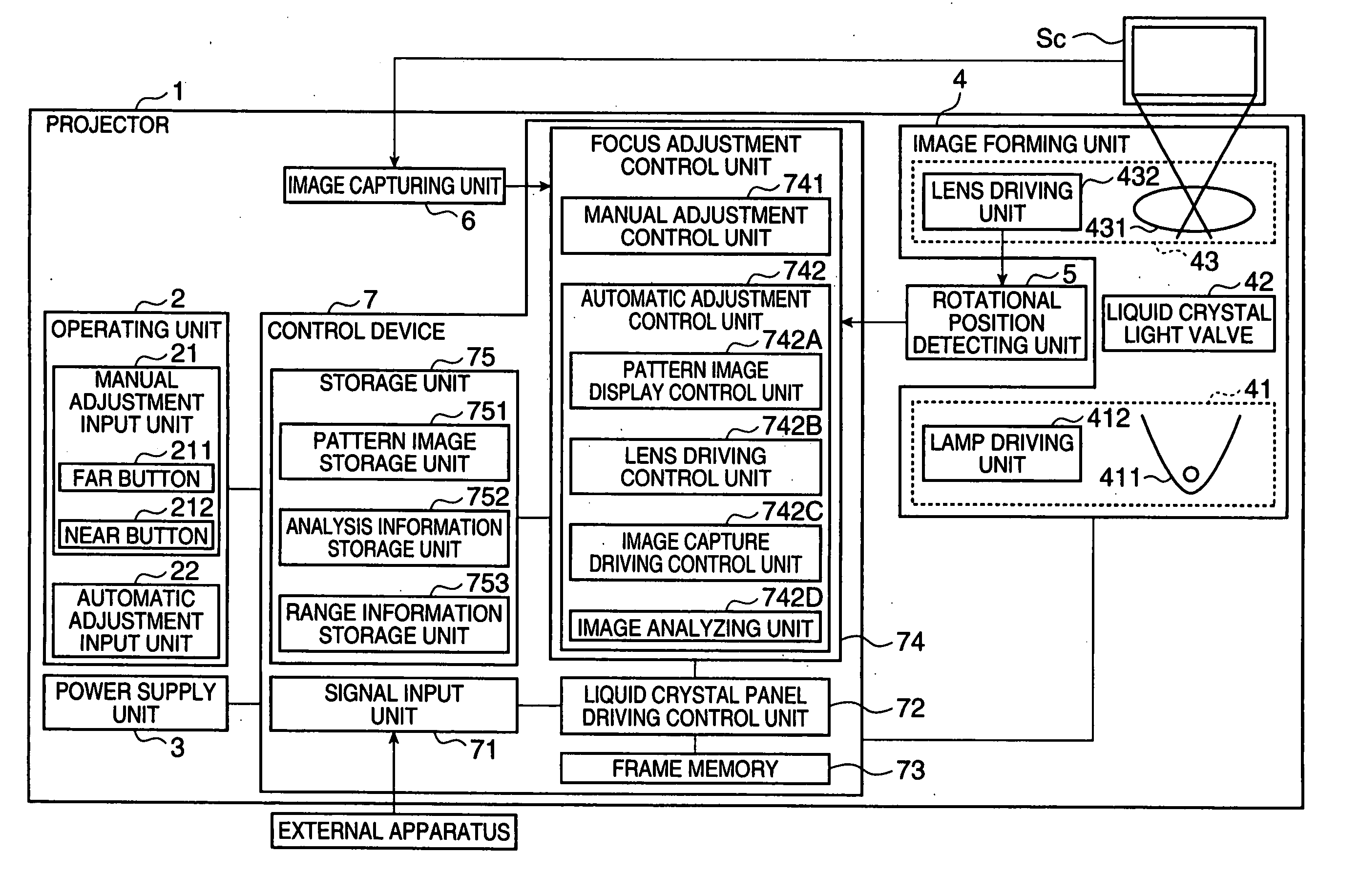
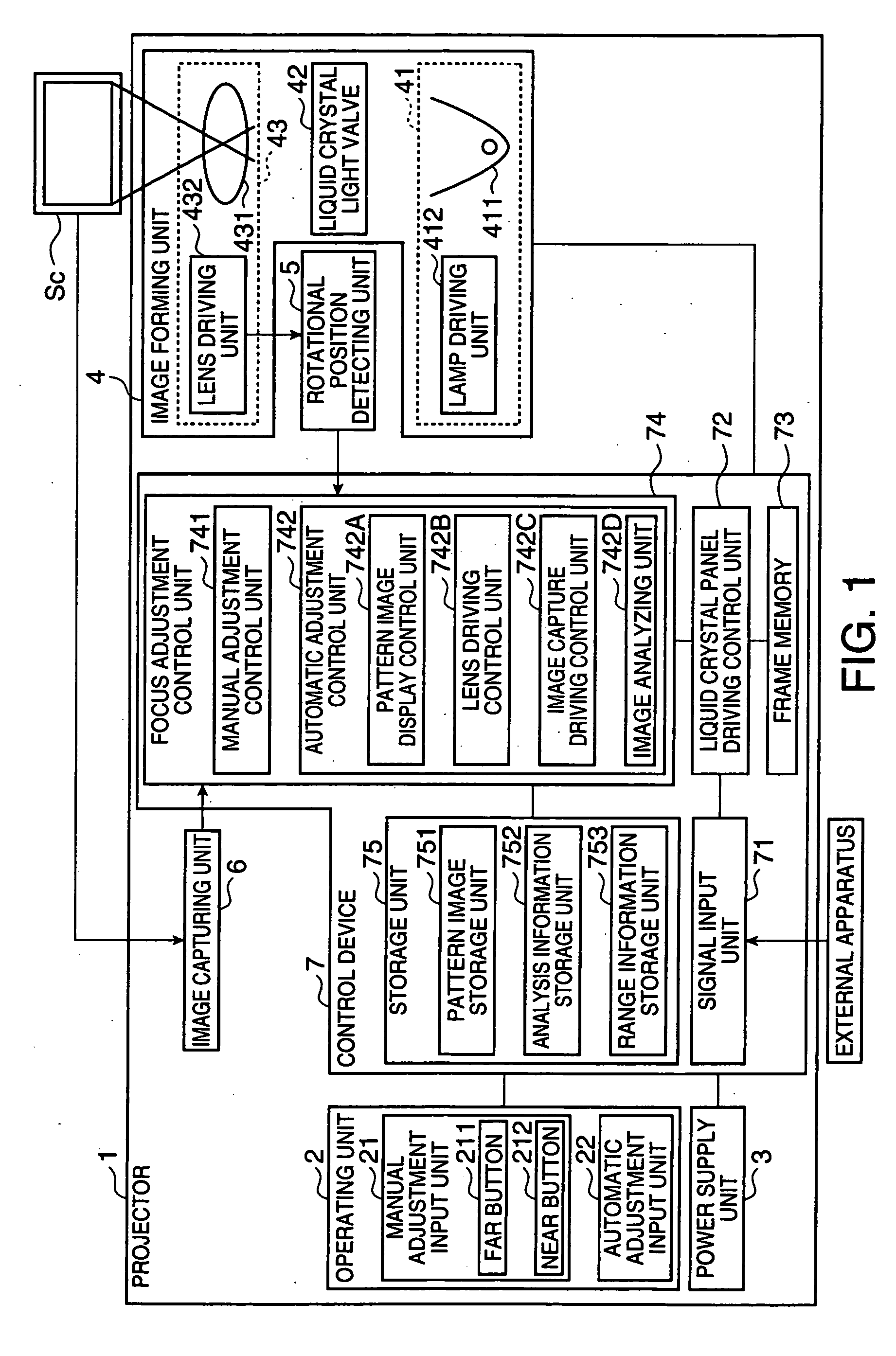
[0077]FIG. 1 is a block diagram illustrating the schematic structure of a projector 1.

[0078] The projector 1 is an apparatus for modulating light beams emitted from a light source according to image information to form an optical image and for enlarging and projecting the formed optical image on a screen Sc (FIG. 1). As shown in FIG. 1, the projector 1 includes an operating unit 2, serving as a setting input unit, a power supply unit 3, an image forming unit 4, a rotational position detecting unit 5, an image capturing unit 6, and a control device 7.

[0079] The operating unit 2 is composed of a remote controller (not shown), or buttons or keys provided in the projector 1, and outputs a predetermined operating signal to the control device 7 when it is operated by a user. As shown in FIG. 1, the operating unit 2 includes a manual adjustment input unit 21 and an ...

second embodiment

[0172] Next, a second embodiment of the invention will be described with reference to the drawings.

[0173] In the second embodiment, the same components as those in the first embodiment have the same reference numerals, and thus a detailed description thereof will be omitted or simply made.

[0174] In the first embodiment, the projector 1 performs both focus adjustment and zoom adjustment for adjusting the outline of a projected image. That is, the rotatable range SP2 in the automatic adjustment control is set, not considering a zoom position which is changed to perform the zoom adjustment of a projected image.

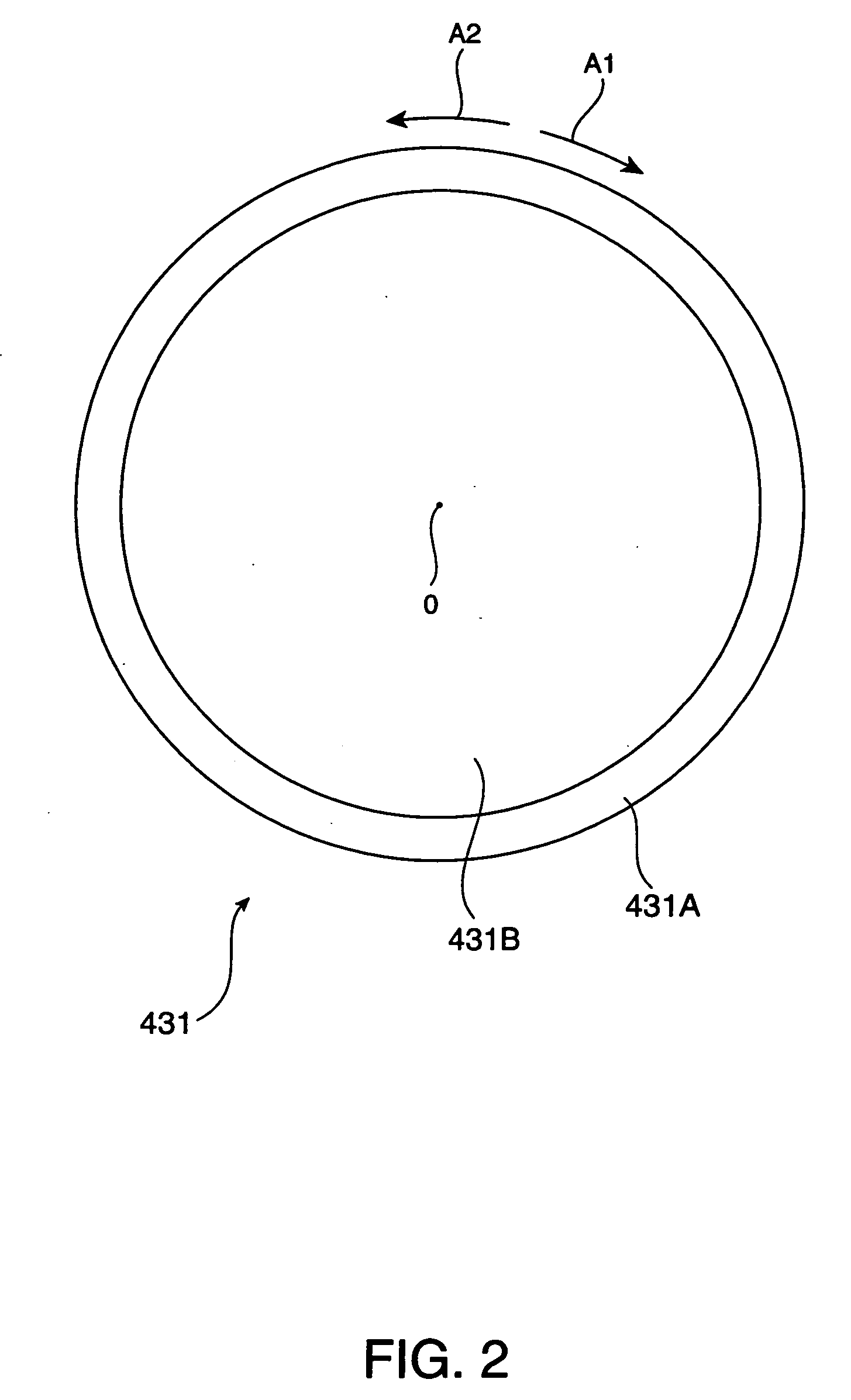
[0175] In contrast, in the second embodiment, the projection lens 431 includes a zoom lens 431D contributing to the zoom adjustment of a projected image and a zoom ring 431C for supporting the zoom lens 431D in addition to the focus ring 431A and the focus lens 431B. Further, in the second embodiment, the rotatable range SP2 in the automatic adjustment control is set consideri...

third embodiment

[0205] Next, a third embodiment of the invention will be described with reference to the drawings.

[0206] In the third embodiment, the same components as those in the first and second embodiments have the same reference numerals, and thus a detailed description thereof will be omitted or simply made.

[0207]FIG. 15 is a block diagram illustrating the schematic structure of a projector 1′ according to the third embodiment.

[0208] In the second embodiment, the operator calculates the shortest tele-end-side focal position FP1B, the longest tele-end-side focal position FP1C, the shortest wide-end-side focal position FP2C, and the longest wide-end-side focal position FP2B, on the basis of the first focal position FP1A and the second focal position FP2A measured. In addition, the operator determines the near-end-side focal position of the calculated focal positions FP1B and FP2C as the near-end-side limit position R3 of the rotatable range SP2, and determines the far-end-side focal positio...


PUM


Abstract

A projector including a light modulating device which modulates light beams emitted from a light source according to image information to form an optical image, a projection optical device, the projection optical device including a projection lens which has a plurality of lenses and enlarges and projects the optical image onto the screen, a focal position changing unit, to perform focus adjustment on the image, a setting input unit through which automatic adjustment information for changing the focal position to an in-focus position where the projected image is in an in-focus state is input, and a focus adjustment control unit which controls the focal position changing unit until the projected image is in the in-focus state.

Description

BACKGROUND [0001] 1. Technical Field [0002] The present invention relates to a projector. [0003] 2. Related Art [0004] There have been known projectors each having a light modulating device for modulating light beams emitted from a light source according to image information to form an optical image and a projection lens for enlarging and projecting the optical image formed by the light modulating device onto a screen. [0005] This type of projector needs to change the relative position of a plurality of lenses constituting the projection lens (to move the position of a focus lens (focal position), contributing to focus adjustment, of the plurality of lens relative to the other lenses in the direction of the optical axis) for the focus adjustment such that the optical image is formed on the screen. In addition, the projector performing this focus adjustment has been disclosed (for example, see JP-A-9-130712). [0006] The projector disclosed in JP-A-9-130712 can perform electromotive f...

Claims


Application Information

Patent Timeline
IPC IPC(8): G03B21/14
CPCG03B21/14G03B21/26H04N9/3194G03B3/10G03B21/142
Inventor KAMIYA, YASUTAKAFURUI, SHIKI
Owner SEIKO EPSON CORP
Why Eureka
Try Eureka