

Exposure apparatus, exposure method, and method for producing device
a technology of exposure apparatus and exposure method, which is applied in the direction of photomechanical apparatus, printing, instruments, etc., can solve the problems of insufficient margin, increased light outflow from the light-transmitting section, and difficulty in matching the substrate surface with respect to the image plane of the projection optical system
- Summary
- Abstract
- Description
- Claims
- Application Information
AI Technical Summary
Benefits of technology
Problems solved by technology
Method used
Image

Examples
first embodiment
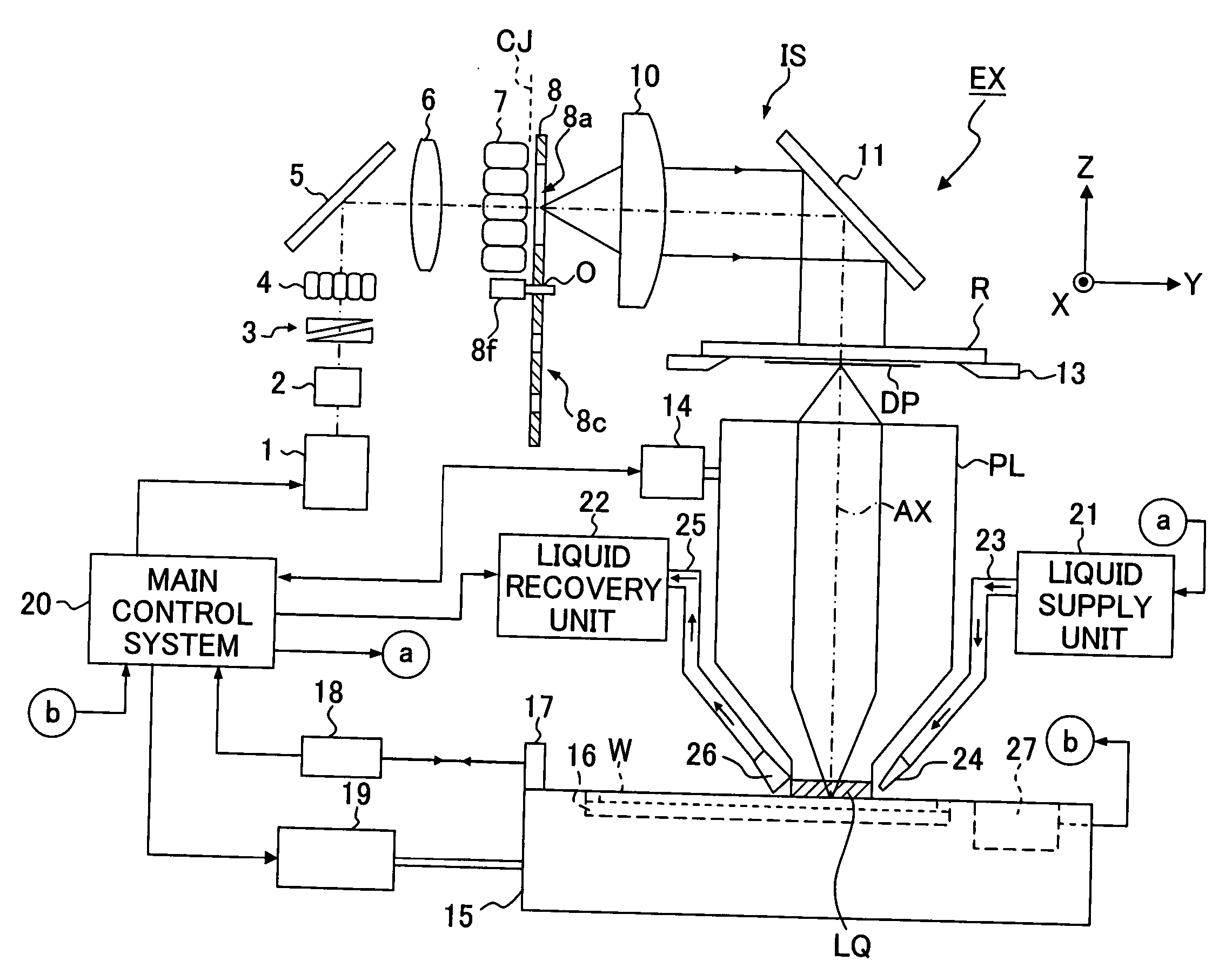
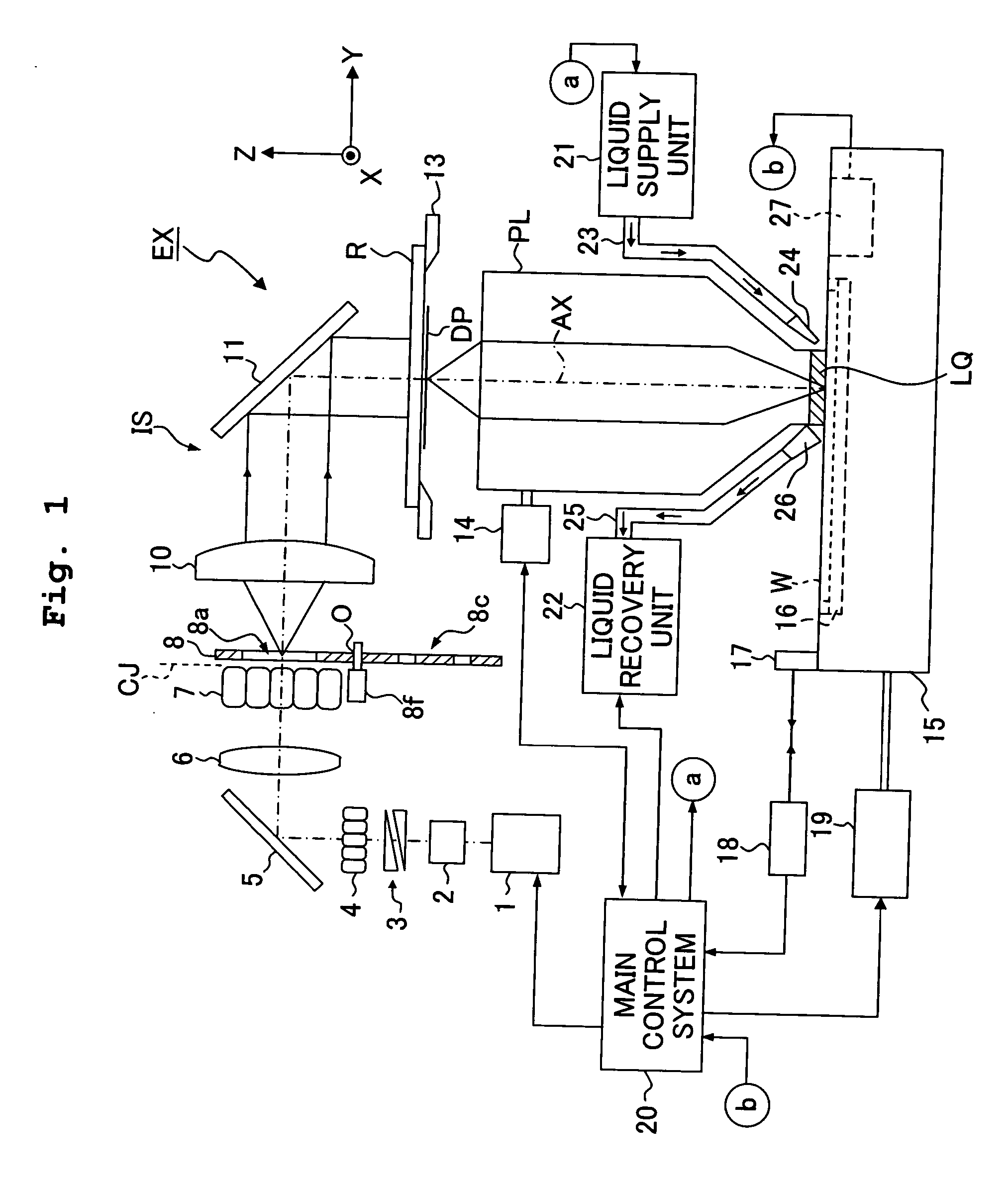
[0081]FIG. 1 shows a schematic arrangement of an exposure apparatus according to a first embodiment of the present invention. The exposure apparatus EX shown in FIG. 1 is an exposure apparatus based on the liquid immersion system in which the exposure is performed through a liquid (pure water) LQ disposed between a projection optical system PL and a wafer W. The exposure apparatus uses a reticle R formed with a circuit pattern DP of a semiconductor element to transfer an image of the circuit pattern DP to the wafer W in the step-and-repeat manner.
[0082] In the following description, the XYZ rectangular coordinate system shown in the drawing is established. An explanation will be made about the positional relationship in relation to the respective members with reference to the XYZ rectangular coordinate system. The XYZ rectangular coordinate system is established so that the X axis and the Y axis are parallel to the wafer W, and the Z axis is established in the direction perpendicul...
second embodiment
[0124] Next, an exposure apparatus according to a second embodiment of the present invention will be explained. The overall structure of the exposure apparatus of this embodiment is constructed in approximately the same manner as the exposure apparatus shown in FIG. 1. However, the structure of the exposure beam sensor 27 differs. In the first embodiment, the exposure beam sensor 27 performs the measuring operation (receiving of the exposure beam) without providing the liquid LQ on the image plane side of the projection optical system PL. However, in the following description, an exposure beam sensor 27 performs the measuring operation through the liquid LQ on the image plane side of the projection optical system PL. As shown in FIG. 3, the exposure beam sensor 27 described in the first embodiment is provided with the irradiation irregularity sensor 36 and the dose sensor 37. In the following description, for the purpose of simplification of the explanation, a case will be principal...
third embodiment
[0137] Next, an exposure apparatus according to a third embodiment of the present invention will be explained. The entire structure of the exposure apparatus of this embodiment is constructed in approximately the same manner as the exposure apparatus shown in FIG. 1, in the same manner as in the second embodiment described above. However, the structure of the exposure beam sensor 27 differs. Also in this embodiment, an explanation will be principally made about an irradiation irregularity sensor provided for the exposure beam sensor 27.
[0138]FIG. 7 shows a schematic arrangement of the irradiation irregularity sensor provided for the exposure apparatus according to the third embodiment of the present invention, wherein FIG. 7A shows a sectional view, and FIG. 7B shows a perspective view illustrating an aperture plate and a plano-convex lens provided for the irradiation irregularity sensor. As shown in FIG. 7A, the irradiation irregularity sensor 50 provided for the exposure apparatu...
PUM
 Abstract
Description
Claims
Application Information