
Heat spreader for display device

a technology of display device and heat spreader, which is applied in the direction of electrical apparatus construction details, casings/cabinets/drawers, transportation and packaging, etc., can solve the problems of large voltages for activation becoming more susceptible to thermal deterioration, difficult heat conduction in directions parallel to the panel face, and difficult to achieve the effect of preventing the flaking of graphite particles and facilitating rework

Inactive Publication Date: 2006-08-03
NEOGRAF SOLUTIONS LLC
View PDF29 Cites 35 Cited by
  • Summary
  • Abstract
  • Description
  • Claims
  • Application Information

AI Technical Summary

Benefits of technology

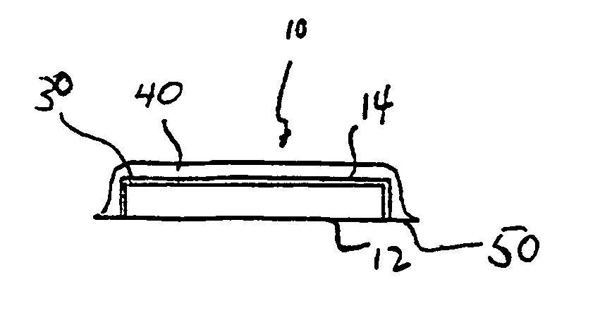
[0020] Another object of the present invention is to provide a heat spreader material which can be used in a display device to ameliorate the temperature differences which occur during use and which can function to manage heat transfer between the display device and a structural chassis.
[0028] In a preferred embodiment, where an adhesive is employed the heat spreader has a release material positioned on each major surface such that the adhesive on each major surface is sandwiched between the heat spreader and the release material. The release material and adhesive are selected to permit a predetermined rate of release of the release material without causing undesirable damage to the heat spreader. Indeed, the adhesive and release material provide an average release load of no greater than about 40 grams per centimeter at a release speed of one meter per second, more preferably no greater than about 10 grams per centimeter at a release speed of one meter per second.

Problems solved by technology

The heat generated in the discharge cells is transferred to the glass forming the base plates, but heat conduction in directions parallel to the panel face is difficult because of the properties of the glass base plate material.
Further, since the temperature difference between activated and nonactivated discharge cells can be high, and the temperature difference between discharge cells generating white light and those generating darker colors also can be high, a stress is applied to the panel unit, causing the conventional plasma display panel to be prone to cracks and breakage.
Thus, those cells having large voltages for activation become more susceptible to thermal deterioration and tend to exacerbate the breakage problem of the panel unit of the plasma display panel.
LEDs present similar issues with respect to heat generation as do PDPs.
Similar issues arise in display devices other than emissive display devices, such as LCDs, where hot spots can limit the effectiveness or life of the device.
However, there is a concern in the electronics industries in general that the use of graphite-based materials can result in graphite particles flaking off, with the result that the flakes can mechanically (i.e., in the same manner as dust particles) interfere with equipment operation and function and, more significantly, that due to the conductive nature of graphite, graphite flakes can electrically interfere with operation of the emissive display device.
Although it is believed that it has been shown that these concerns are misplaced, they still survive.
Also, the use of adhesives to attach a graphite heat spreader to an emissive display device can be disadvantageous at times. More specifically, in the event rework (i.e., removal and replacement of the heat spreader) is needed, the adhesive bond can be stronger than the structural integrity of the graphite sheet; in this situation, the graphite sheet cannot always be cleanly lifted off the panel without the use of scrapers or other like tools, which can be time consuming and potentially damaging to the graphite sheet, the panel or both.
Another issue which often arises is in attachment of a metallic, such as aluminum, chassis to the display panel, with the heat spreader disposed therebetween.
Because of this, the adhesion requirements of the tape material are extreme, requiring use of a material which is often not economically efficient.

Method used

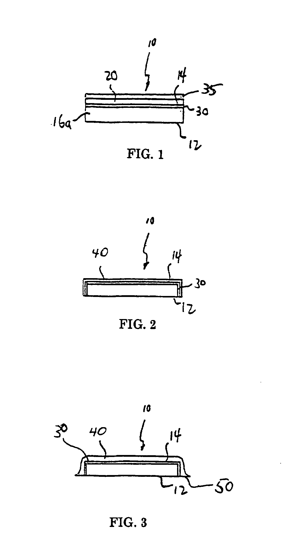
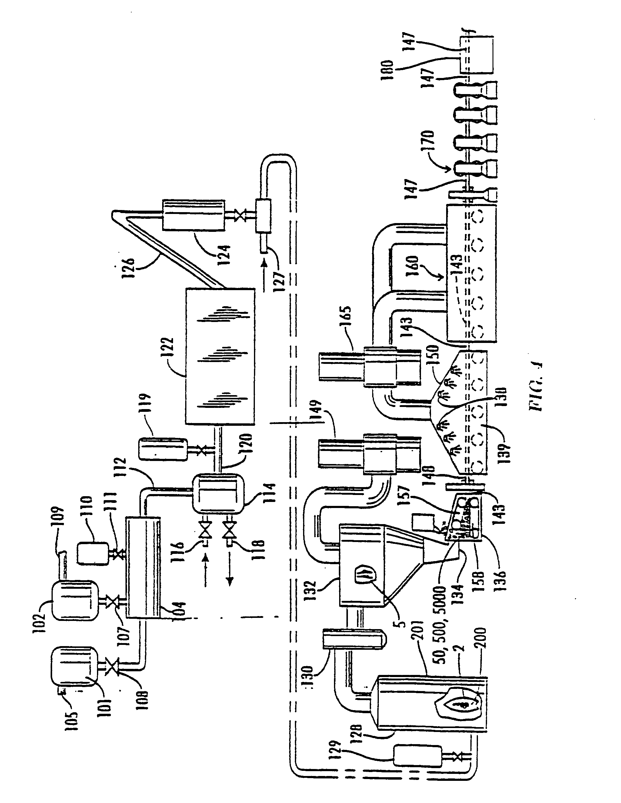

Image

  • Heat spreader for display device
  • Heat spreader for display device
  • Heat spreader for display device

Examples


Embodiment Construction

[0035] Graphite is a crystalline form of carbon comprising atoms covalently bonded in flat layered planes with weaker bonds between the planes. In obtaining source materials such as the above flexible sheets of graphite, particles of graphite, such as natural graphite flake, are typically treated with an intercalant of, e.g. a solution of sulfuric and nitric acid, where the crystal structure of the graphite reacts to form a compound of graphite and the intercalant. The treated particles of graphite are hereafter referred to as “particles of intercalated graphite.” Upon exposure to high temperature, the intercalant within the graphite decomposes and volatilizes, causing the particles of intercalated graphite to expand in dimension as much as about 80 or more times its original volume in an accordion-like fashion in the “c” direction, i.e. in the direction perpendicular to the crystalline planes of the graphite. The expanded (otherwise referred to as exfoliated) graphite particles are...


PUM


Abstract

A heat spreader for a display device, such as a plasma display panel, a light emitting diode or a liquid crystal display, which includes at least one sheet of compressed particles of exfoliated graphite having two major surfaces.

Description

TECHNICAL FIELD [0001] The present invention relates to a heat spreader formed of compressed particles of exfoliated graphite useful for a display device, such as a plasma display panel (PDP), a liquid crystal display (LCD), a light emitting diode (LED), and the like, and the unique thermal issues occasioned by these devices. BACKGROUND OF THE ART [0002] A plasma display panel is a display apparatus which contains a plurality of discharge cells, and is constructed to display an image by applying a voltage across electrodes discharge cells thereby causing the desired discharge cell to emit light. A panel unit, which is the main part of the plasma display panel, is fabricated by bonding two glass base plates together in such a manner as to sandwich a plurality of discharge cells between them. [0003] In a plasma display panel, each of the discharge cells which are caused to emit light for image formation generate heat and each thus constitutes a source of heat, which causes the tempera...

Claims


Application Information

Patent Timeline
Patent Type & Authority Applications(United States)
IPC IPC(8): H05K7/20
CPCH05K5/02Y10T428/30H05K7/20963C01B32/20H01J9/24H01J11/34H01J11/40H01J17/28H01J17/49H01J2211/66
Inventor CAPP, JOSEPH P.CLOVESKO, TIMOTHYNORLEY, JULIANSMALC, MARTIN DAVIDREIS, BRADLEY E.
Owner NEOGRAF SOLUTIONS LLC
Learn More