Method and apparatus for chemical plasma processing of plastic container

Inactive Publication Date: 2006-08-03
TOYO SEIKAN KAISHA LTD
View PDF8 Cites 3 Cited by
  • Summary
  • Abstract
  • Description
  • Claims
  • Application Information

AI Technical Summary

Benefits of technology

[0012] According to the present invention, the plastic container is treated with the plasma while being cooled effectively suppressing the plastic container such as the plastic bottle from being deformed

Problems solved by technology

However, if the plasma treatment is conducted relying upon the above method by supplying large energy of microwave or for exte

Method used


Image

  • Method and apparatus for chemical plasma processing of plastic container
  • Method and apparatus for chemical plasma processing of plastic container
  • Method and apparatus for chemical plasma processing of plastic container

Examples


Embodiment Construction

(Plasma-Treating Apparatus)

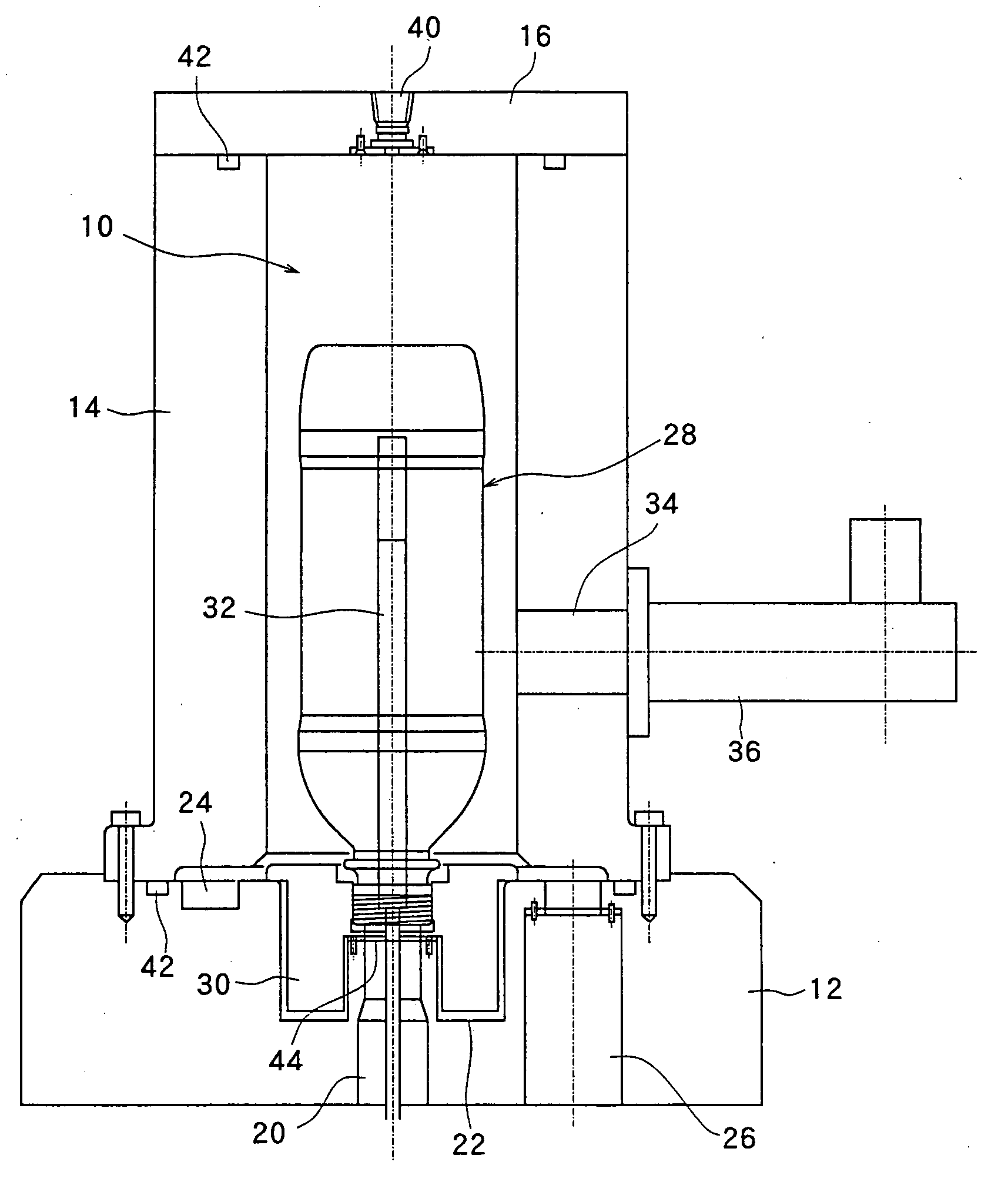
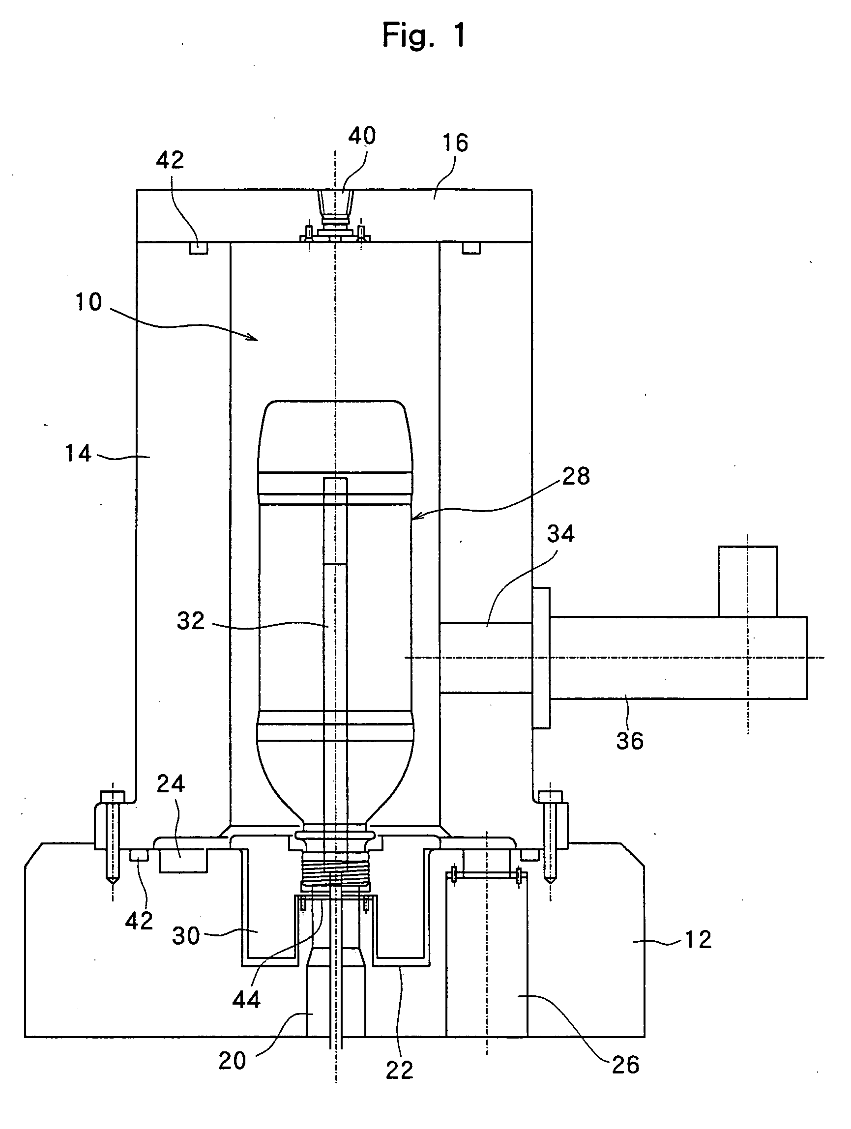
[0018]FIG. 1 illustrates the structure of the plasma-treating apparatus used for favorably treating a plastic container and, particularly, the inner surface of the plastic container with a plasma, wherein a plasma-treating chamber which as a whole is designated at 10 is constituted by an annular base plate 12, a cylindrical side wall 14, and a ceiling wall 16 closing the upper part of the cylindrical side wall 14.

[0019] A first exhaust portion 20 is formed in the central part of the annular base plate 12, an annular recessed portion 22 is formed in the upper surface of the base plate 12 so as to surround the first exhaust portion 20, and an annular groove 24 is formed surrounding the annular recessed portion 22, the annular groove 24 being communicated with the second exhaust portion 26.

[0020] In the annular recessed portion 22, there is contained a bottle holder 30 for holding a bottle 28 upside down. As will be obvious from FIG. 1, the neck portion o...


PUM

PropertyMeasurementUnit
Pressureaaaaaaaaaa
Diameteraaaaaaaaaa
Frequencyaaaaaaaaaa

Abstract

A method of treating plastic containers with a chemical plasma by forming a film by CVD on the plastic containers by generating a glow discharge by feeding a gas for plasma treatment and energy such as microwaves for plasmatization into a plasma-treating chamber, wherein the plastic containers are cooled. This method effectively suppresses the plastic containers from being deformed, is capable of forming the film by CVD on the inner surfaces of the plastic containers consecutively for extended periods of time, and greatly enhances the productivity.

Description

TECHNICAL FIELD [0001] The present invention relates to a method of treating plastic containers with a chemical plasma relying upon a glow discharge by using microwaves or high frequency waves, and to an apparatus therefor. BACKGROUND ART [0002] The chemical vapor deposition (CVD) is a technology for precipitating, like a film, a reaction product on the surface of a base body by the vapor-phase growth in a high-temperature atmosphere by using a starting gas which does not undergo the reaction at normal temperature, has been widely employed in the production of semiconductors and in reforming the surfaces of metals, glasses and ceramics, and has nowadays been employed even for reforming the surfaces of plastic containers such as plastic bottles and, particularly, for improving gas shut-off property. [0003] The plasma CVD is for growing a thin film by utilizing a plasma and basically comprises a process in which a gas containing a starting gas is discharged by using electric energy un...

Claims


Application Information

Patent Timeline
IPC IPC(8): H05H1/24H01S3/00C23C16/04C23C16/511
CPCC23C16/045C23C16/463C23C16/511H01J37/32082H01J37/32192H01J37/3244C23C16/505H01L21/205
Inventor KOBAYASHI, AKIRAYAMADA, KOJIAIHARA, TAKESHIKURASHIMA, HIDEO
Owner TOYO SEIKAN KAISHA LTD
Why Eureka
Try Eureka