Al technical title is built by PatSnap Al team. It summarizes the technical point description of the patent document.
a digital dc/dc converter and control technology, applied in the direction of pulse generator, pulse technique, code conversion, etc., can solve the problems of large size of the conductor to handle current and the associated isup>2/sup>r power loss
Inactive Publication Date: 2006-08-03
SILICON LAB INC
View PDF30 Cites 58 Cited by
Summary
Abstract
Description
Claims
Application Information
AI Technical Summary
This helps you quickly interpret patents by identifying the three key elements:
Problems solved by technology
Method used
Benefits of technology
Problems solved by technology
If this conversion is facilitated at a power supply and then connected to a remote microprocessor on a printed circuit board, the size of the conductor to handle the current and the associated I2R power loss would be large.
Method used
Image
Click on the blue label to locate the original text in one second.
Reading with bidirectional positioning of images and text.
Examples
Embodiment Construction
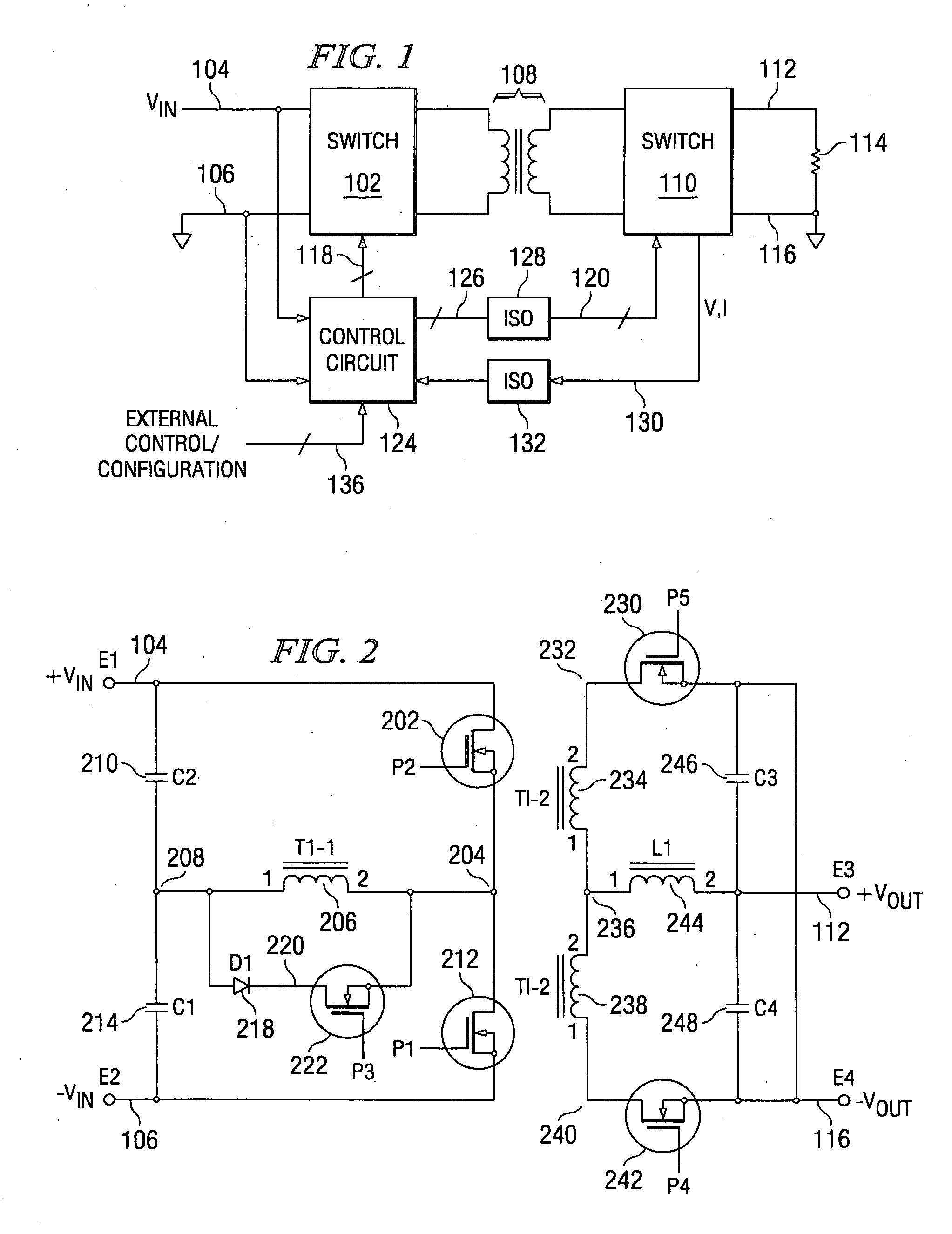
[0077] Referring now to FIG. 1, there is illustrated a top level schematic diagram for the switching power supply of the present embodiment, which in this Fig. is illustrated as a half bridge power supply. The main portion of the power supply comprises a primary switch group 102 that is operable to receive an input voltage on a node 104, this being a DC voltage, and ground on a node 106. The primary switch group 102 is coupled through an isolation transformer 108 to a secondary switch group 110. The secondary switch group 110 is operable to drive an output voltage node 112 that is connected to one terminal of a load 114, the secondary switch group 110 also having a ground connection on a node 116, the load 114 disposed between the node 112 and the node 116. The two switch groups 102 and 110 are operable to operate in conjunction with various pulse inputs on a control bus 118 associated with the primary switch group 102 and with various pulse inputs on a control bus 126 associated wi...
PUM
Abstract
A power converter is disclosed for receiving an input voltage and converting it to a DC output voltage at a different voltage level than the input voltage. It includes a switching power converter for receiving the input voltage on an input and converting the input voltage to an output as the DC output voltage in response to pulse control signals. A switching controller is provided for generating the pulse control signals during a switching cycle and a processor controls the switching controller to define the length and initiation of the switching cycle. A communication interface interfaces with a first data communication bus for receiving data therefrom and with a second communication bus for receiving timing information therefrom. The processor and the switching controller operate in either a first operating mode to control the switching controller and the generation of the pulse control signals independent of timing information, or in a second operating mode to control the timing of the generation of the pulse control signals generated by the switching controller in response to timing information received from the communication bus.
Description
CROSS-REFERENCE TO RELATED APPLICATIONS [0001] This application is a Continuation-in-part application of U.S. Ser. No. 11 / 172,358, filed Jun. 30, 2005, entitled “FINITE STATE MACHINE DIGITAL PULSE WIDTH MODULATOR FOR A DIGITALLY CONTROLLED POWER SUPPLY,” (Atty. Dkt. CYGL 27,150), which is a Continuation-in-part application of U.S. Ser. No. 11 / 096,597, filed on Mar. 31, 2005, entitled “DIGITAL PWM CONTROLLER” (Atty. Dkt. CYGL 27,074) and it is related to U.S. patent application Ser. No. 11 / 096,598, filed Mar. 31, 2005, and entitled “PID BASED CONTROLLER FOR DC-DC CONVERTER WITH POST-PROCESSING FILTERS” (Atty. Dkt. CYGL 27,105) and U.S. patent application Ser. No. 11 / 096,853, filed Mar. 31, 2005, and entitled “DIGITAL POWER SUPPLY CONTROLLER WITH VOLTAGE POSITIONING” (Atty. Dkt. No. CYGL-27,111), both of which are incorporated herein by reference in their entirety and claims priority in Provisional Application No. 60 / 591,463, filed Jul. 27, 2004, which is incorporated herein by refere...
Claims
Application Information
Patent Timeline
Application Date:The date an application was filed.
Publication Date:The date a patent or application was officially published.
First Publication Date:The earliest publication date of a patent with the same application number.
Issue Date:Publication date of the patent grant document.
PCT Entry Date:The Entry date of PCT National Phase.
Estimated Expiry Date:The statutory expiry date of a patent right according to the Patent Law, and it is the longest term of protection that the patent right can achieve without the termination of the patent right due to other reasons(Term extension factor has been taken into account ).
Invalid Date:Actual expiry date is based on effective date or publication date of legal transaction data of invalid patent.
Patent Type & Authority Applications(United States)