Ultrasonographic device and ultrasonographic method

a technology of ultrasonography and ultrasonography, which is applied in the field of ultrasonic imaging devices, can solve the problems of difficult to accurately estimate a local displacement and difficult to perform idealistic correction for the entire image, and achieve the effects of improving spatial resolution, improving contrast resolution, and improving spatial resolution

Inactive Publication Date: 2006-08-03
HITACHI MEDICAL CORP
View PDF5 Cites 10 Cited by
  • Summary
  • Abstract
  • Description
  • Claims
  • Application Information

AI Technical Summary

Benefits of technology

[0015] In the aperture synthesis, there occurs interference between signals to be synthesized, and if there occurs positional displacement larger than a quarter of a wavelength, the signal is degraded after synthesis. On the other hand, in the case of compound imaging, there occurs no interference between signals to be synthesized, so that positional displacement smaller than the width of an envelop of an envelop signal does not cause any signal degradation. Generally in the currently available ultrasonic imaging devices, the width of an envelop is only several times larger than the wavelength.
[0016] Since there are two image synthesis methods currently available, namely the compound imaging method and synthetic aperture method, and the two methods have different merits respectively, and there has been a desire for development of an imaging method having the merits provided by the two conventional methods as described above. In other words, the desire is to realize improvement of contrast resolution and improvement of spatial resolution at the same time and also to realize an imaging method in which an image is little degraded due to movement of a scanned object.
[0017] In the currently available ultrasonic imaging devices, a transfer function of the ultrasonic probe 32 is equivalent to a width of several waves on the time axis because the width is limited in the frequency space. In ultrasonic imaging, influence by a transfer function of the ultrasonic probe 32 occurs twice because of transmission of ultrasonic signal waves from the ultrasonic probe 32 and receiving of ultrasonic waves reflected by a scanned body with the ultrasonic probe 32, and therefore a width of the envelop is in the range from about 2 to 4 waves. In other words, influence caused by movement of a scanned object in the coherent case is around 10 times larger than that in the incoherent case. If a displacement range between synthesized images can idealistically be corrected pixel by pixel, the influence caused by movement of an scanned object could be corrected by any of the two known methods. However, since the corrected value is not always precise because of influences by noises, and there is displacement also in a direction perpendicular to the tomographic image, it is difficult to accurately estimate a local displacement.
[0018] In the present invention, it is not aimed to perfectly correct a local displacement, and correction is carried out based on the large scale displacement rate. That is to say, when a displacement is small (for instance, smaller than a quarter of a wavelength), signal synthesis is executed based on RF data, and when the displacement is larger, the signal synthesis is carried out based on the envelop detection signals. A degree of each displacement can be determined on recognition of correlation of RF data between images in different frames. Furthermore, any of signal synthesis based on RF data and signal synthesis of envelop detection signals can freely be selected by controlling a reference frequency for heterodyne detection.

Problems solved by technology

Therefore, it is difficult to perform idealistic correction for the entire image.
However, since the corrected value is not always precise because of influences by noises, and there is displacement also in a direction perpendicular to the tomographic image, it is difficult to accurately estimate a local displacement.

Method used


Image

  • Ultrasonographic device and ultrasonographic method
  • Ultrasonographic device and ultrasonographic method
  • Ultrasonographic device and ultrasonographic method

Examples


first embodiment

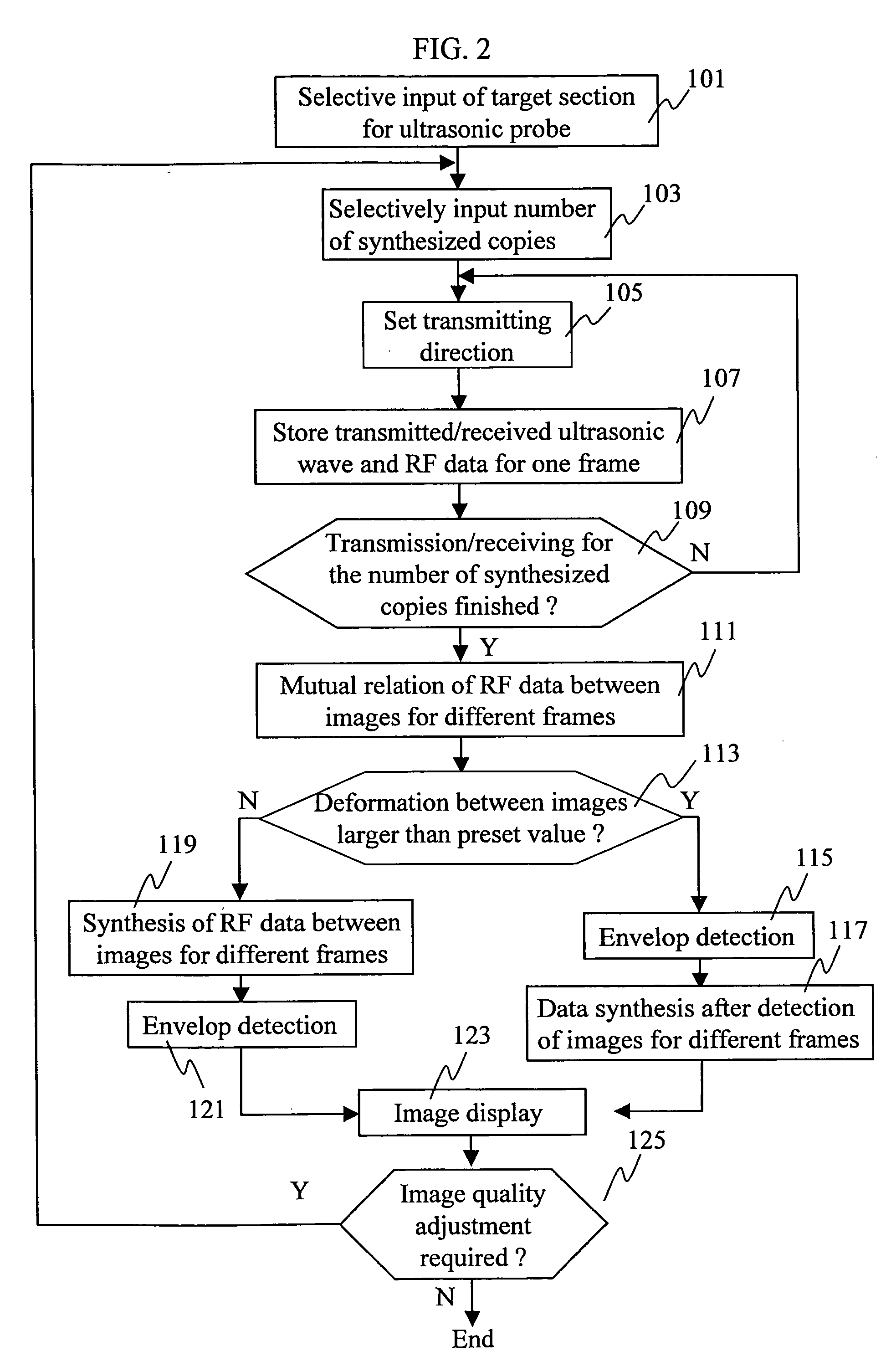
[0036]FIG. 2 is a flow chart illustrating a signal processing flow in the ultrasonic imaging device according to a first embodiment of the present invention.

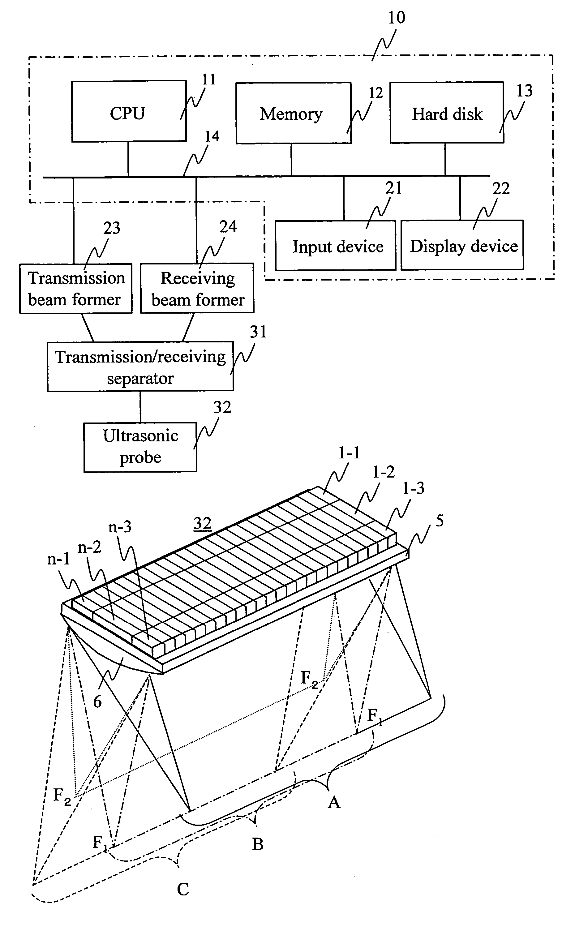
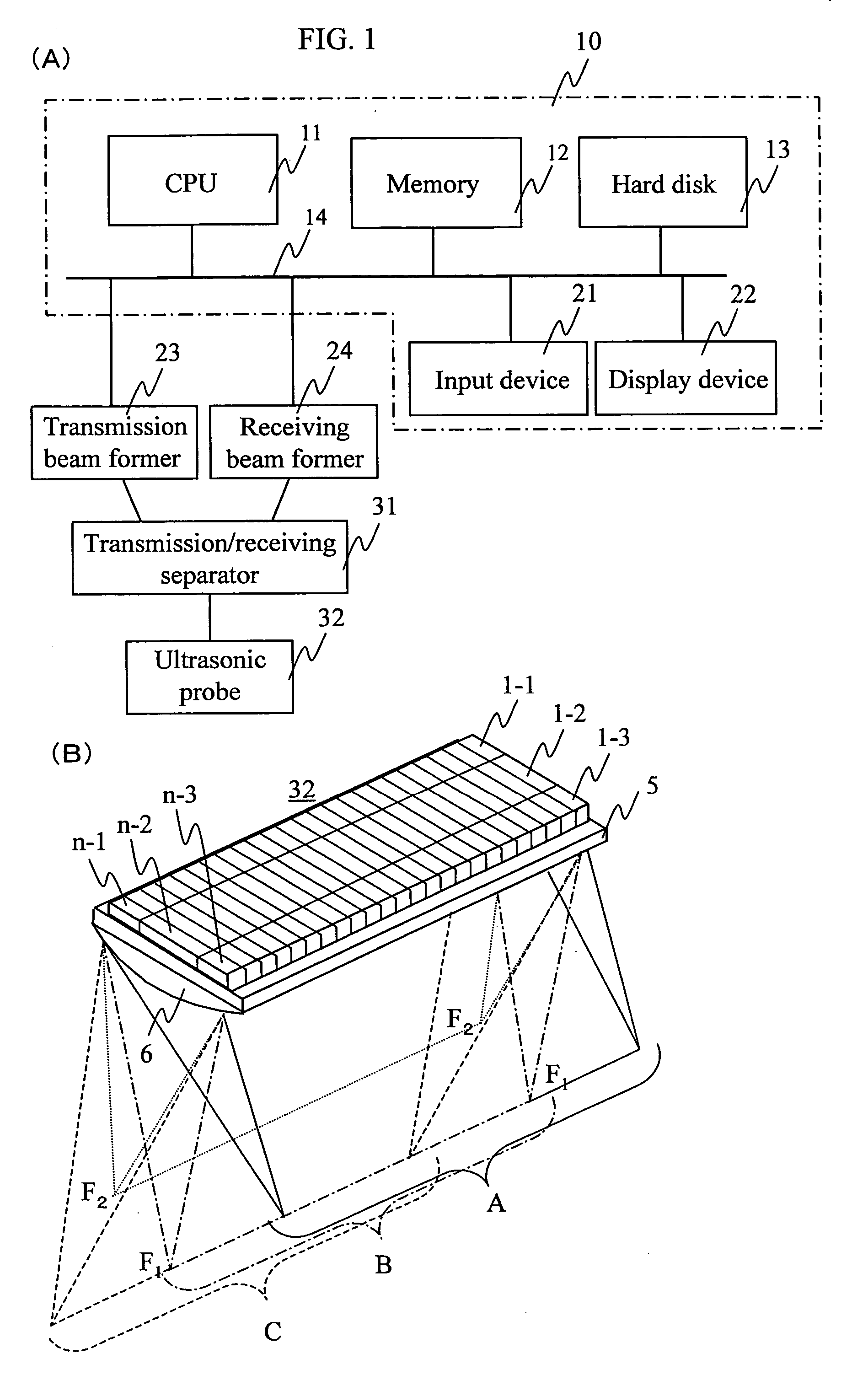
[0037] Reference numeral 101 indicates a preparation step, in which data such as a type of an ultrasonic probe to be used and codes indicating objective portions of an object to be imaged is inputted through an input device 21. Reference numeral 103 indicates a step of specifying the number of image frames to be synthesized for the target portions of the scanned object, in which the data is inputted through the input device 21. The number of frames to be synthesized is at least 3 or more. The number of frames may be in the range from 7 to around 15. As the number of frames to be synthesized increases, effects of image synthesis and defects caused by synthesis increase, and therefore the number of frames should preferably be determined according to an object to be imaged (movement of the object to be imaged).

[0038] Reference nu...

second embodiment

[0055]FIG. 3 is a flow chart illustrating a signal processing flow in an ultrasonic imaging device according to a second embodiment of the present invention. In FIG. 3, the same reference numbers are assigned to the corresponding steps in FIG. 2.

[0056] Also in the second embodiment, like in the first embodiment, a type of a ultrasonic probe to be used and a target portion of a scanned object are set (step 101), the number of frames to be imaged for image synthesis is specified (step 103), a ultrasonic signal wave transmission direction toward each target portion to be imaged is set (step 105), RF data for transmitted and received ultrasonic signal waves for one frame is stored (step 107), the number of imaged frames is checked (step 109), and the processing sequence is repeated until the number of imaged frames reaches the number of frames specified in step 103. Then correlation of RF data between images for different frames in step 111 is computed.

[0057] Reference numeral 114 ind...

third embodiment

[0074]FIG. 4 is a flow chart illustrating a signal processing flow in an ultrasonic imaging device according to a third embodiment of the present invention. In FIG. 4, the same reference numerals are assigned to the steps of executing the same processing steps shown in FIG. 2 or 3.

[0075] In the second embodiment, a reference frequency for heterodyne detection is automatically selected according to correlation of RF data between images for different frames (step 114). In the third embodiment, however, a user can change the reference frequency for heterodyne detection based on the user's policy in step 104, which is the only difference from the second embodiment. Other processing steps are the same as those shown in the processing flow shown in FIG. 3.

[0076]FIG. 11 shows an appearance of an input device operated by a user in step 104 in the third embodiment. Reference numeral 51 indicates an operation button, which can be moved in the horizontal direction along a travel guide 52. Re...


PUM


Abstract

In an ultrasonic imaging device having an image synthesizing unit, correlation between images to be synthesized is computed for balancing between an improvement in contrast resolution and an improvement in spatial resolution, and an amount of displacement between the images is computed. When the amount of displacement is large, the signals after envelop detection are synthesized. When the amount of displacement is small, RF signals are synthesized. Alternatively, the mixing frequency may be variable according to the amount of displacement, and the balance between an improvement in spatial resolution and that in contract resolution is achieved according to a degree of the positional displacement.

Description

FIELD OF THE INVENTION [0001] The present invention relates to an ultrasonic imaging device used for medical diagnosis or other purposes, and more specifically to a technique for obtaining a high quality tomographic image referred generally to as a compound scan image displayed as one image by synthesizing image signals obtained by scanning a scanned object from various angles. DESCRIPTION OF THE RELATED ART [0002] The ultrasonic imaging device brings an ultrasonic probe into contact with a surface of a scanned object, transmits ultrasonic waves to the object from the probe, receives reflected waves (echo signals) from the inside of the object, and displays tomographic images showing a state of various sections of the object based on the echo signals, which are used for medial diagnosis or other purposes. [0003]FIG. 1(A) is a view illustrating the general configuration of an ultrasonic imaging device. Reference numeral 10 indicates an control unit such as a personal computer. Design...

Claims


Application Information

Patent Timeline
Patent Type & Authority Applications(United States)
IPC IPC(8): A61B8/06A61B8/00G01S15/89
CPCA61B8/00G01S7/52077G01S15/8995
Inventor AZUMA, TAKASHIUMEMURA, SHIN-ICHIROBABA, HIROTAKA
Owner HITACHI MEDICAL CORP
Why Eureka
Try Eureka