Swaging-optimized baseplate for disk drive head suspension

a technology for suspensions and disk drives, applied in the direction of support for heads, record information storage, instruments, etc., can solve the problems of affecting the operation performance of the suspension, and being observed to be particularly prevalent, so as to achieve the effect of reducing the deformation of the actuator arm

Inactive Publication Date: 2006-08-10
HUTCHINSON TECH
View PDF20 Cites 16 Cited by
  • Summary
  • Abstract
  • Description
  • Claims
  • Application Information

AI Technical Summary

Benefits of technology

[0006] The present invention is a baseplate for swaging a disk drive head suspension to an actuator arm having a thickness and a neutral axis. The baseplate includes a boss tower having an outer diameter high point configured to be located within about ±6% of the arm thickness from the neutral axis when swaged to an arm. The baseplate is optimized to produce relatively little actuator arm deformation during the swaging process. Gram changes, z-height variations and other detrimental consequences of the arm deformation are thereby reduced.

Problems solved by technology

Unfortunately, this swaging process can result in deformation of the actuator arm.
These swaging-induced z-height variations and gram changes can detrimentally affect the operational performance of the suspensions.
These problems have been observed to be especially prevalent in arms, typically at the ends of a multi-arm stack, having only one suspension swaged thereto.

Method used


Image

  • Swaging-optimized baseplate for disk drive head suspension
  • Swaging-optimized baseplate for disk drive head suspension
  • Swaging-optimized baseplate for disk drive head suspension

Examples


Embodiment Construction

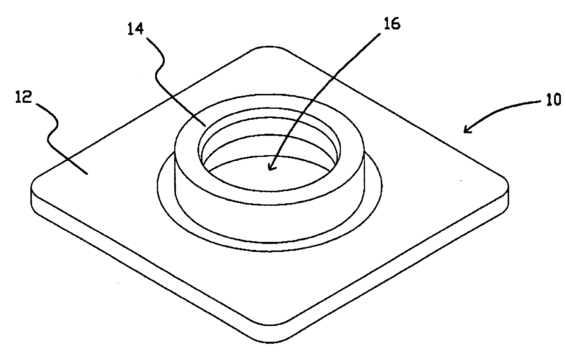
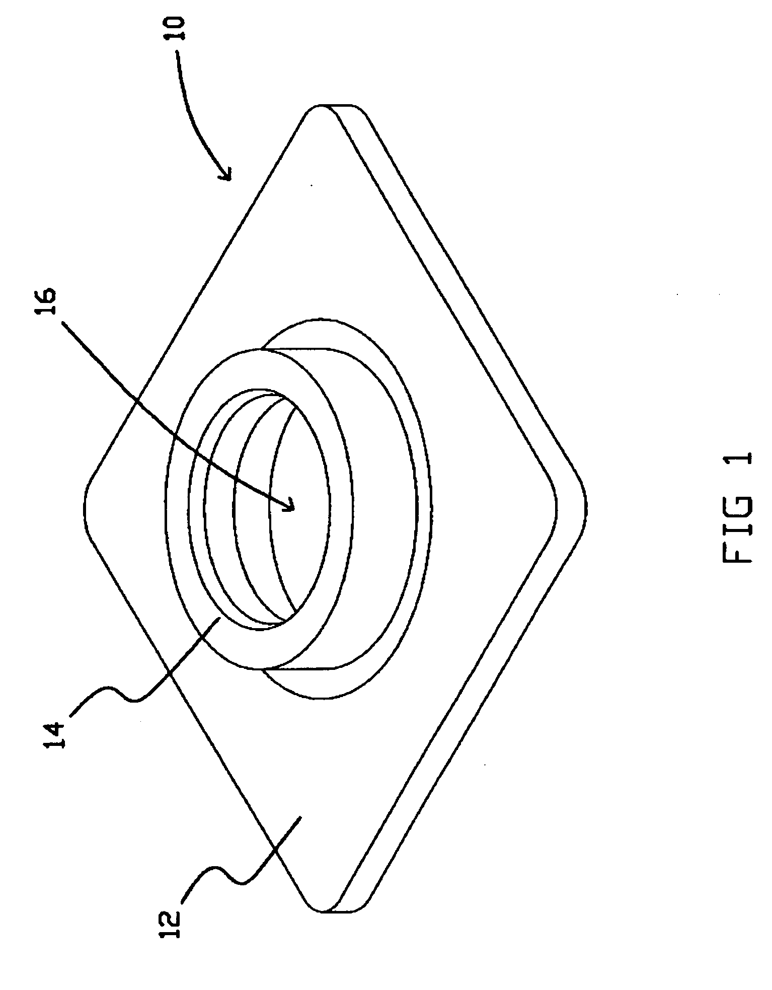
[0011]FIG. 1 is an illustration of a baseplate 10 that can be configured in accordance with the present invention to produce relatively little or minimal swaging-induced deformation in an actuator arm to which it is swaged. As shown, baseplate 10 includes a generally flat flange 12 and a tubular boss tower 14 that extends from the flange and surrounds a swaging hole 16. Baseplates such as 10 are typically manufactured from stainless steel by stamping processes, although other materials and manufacturing methods can also be used.

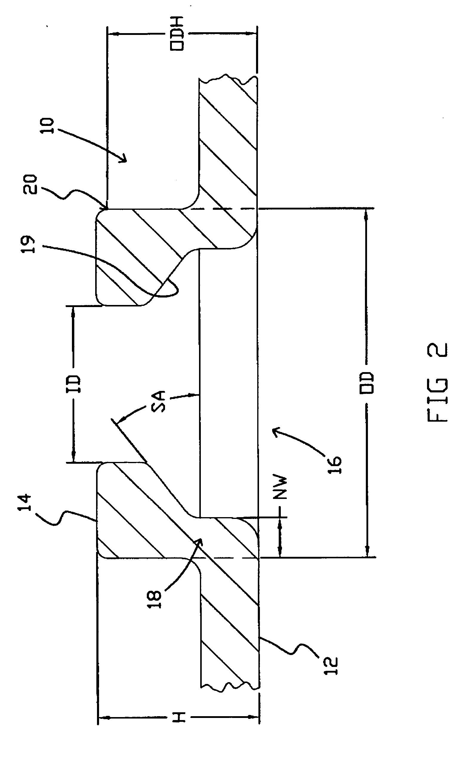
[0012]FIG. 2 is a cross sectional illustration of the baseplate 10 with the boss tower 14 shown in greater detail. As shown, the tower 14 includes a neck 18 and generally increases in cross sectional dimension (into the hole 16) with increasing distance from the flange 12. The tower 14 has a width NW at the neck 18. The cross sectional dimension of the tower increases at a stamping angle SA. In the illustrated embodiment the angled surface. 19 of the tower 1...


PUM

PropertyMeasurementUnit
thicknessaaaaaaaaaa
thicknessaaaaaaaaaa
ODaaaaaaaaaa

Abstract

A baseplate for swaging a disk drive head suspension to an arm having a thickness and a neutral axis. The baseplate includes a boss tower having an outer diameter high point configured to be located within about ±6% of the arm thickness from the neutral axis when swaged to an arm.

Description

REFERENCE TO RELATED APPLICATION [0001] This application is a continuation of application Ser. No. 10 / 686,183, filed on Oct. 15, 2003, and entitled “Swaging-Optimized Baseplate For Disk Drive Head Suspension,” and which is hereby incorporated by reference in its entirety.FIELD OF THE INVENTION [0002] The present invention relates generally to attachment structures such as baseplates for disk drive head suspensions. BACKGROUND OF THE INVENTION [0003] Swage baseplates are widely used in disk drives to attach head suspensions to E-blocks, C-blocks or other actuator arms. Examples of these attachment structures and associated assembly methods are disclosed in the Wang et al. U.S. Patent Application Publication No. 2002 / 0145830, and the Hanrahan et al. U.S. Pat. Nos. 6,033,755 and 6,183,841, all of which are incorporated herein by reference. [0004] Briefly, baseplates include a generally flat flange and a tubular boss tower extending from the flange. The flange is typically welded to a m...

Claims


Application Information

Patent Timeline
Patent Type & Authority Applications(United States)
IPC IPC(8): G11B5/127G11B5/48
CPCY10T29/49025G11B5/4833
Inventor ZHANG, YIDUOLINNERTZ, WADE A.FOSSUM, RANDOLPH EDWARDVAN SLOUN, SHANE J.
Owner HUTCHINSON TECH
Why Eureka
Try Eureka