Exhaust gas cooler

a technology of exhaust gas cooler and cooler body, which is applied in the direction of indirect heat exchangers, machines/engines, lighting and heating apparatus, etc., can solve the problems of increasing the space required, and increasing the boiling of liquid coolant. , to achieve the effect of increasing the heat exchange efficiency of exhaust gas cooler

Inactive Publication Date: 2006-08-10
HONEYWELL INT INC
View PDF3 Cites 48 Cited by
  • Summary
  • Abstract
  • Description
  • Claims
  • Application Information

AI Technical Summary

Benefits of technology

[0013] Thus an object of the present invention is to increase the heat-exchange efficiency of an exhaust gas cooler.

Problems solved by technology

This problem becomes more acute as an increasing number of stamped plate pairs are utilized in an exhaust gas cooler.
It can also create local areas of high surface temperature which can cause boiling of the liquid coolant.
However this involves additional external components which increases the space required in the frequently cramped engine layout and does not in any case cater for stamped plate exhaust gas coolers.

Method used


Image

  • Exhaust gas cooler
  • Exhaust gas cooler
  • Exhaust gas cooler

Examples


embodiment 40

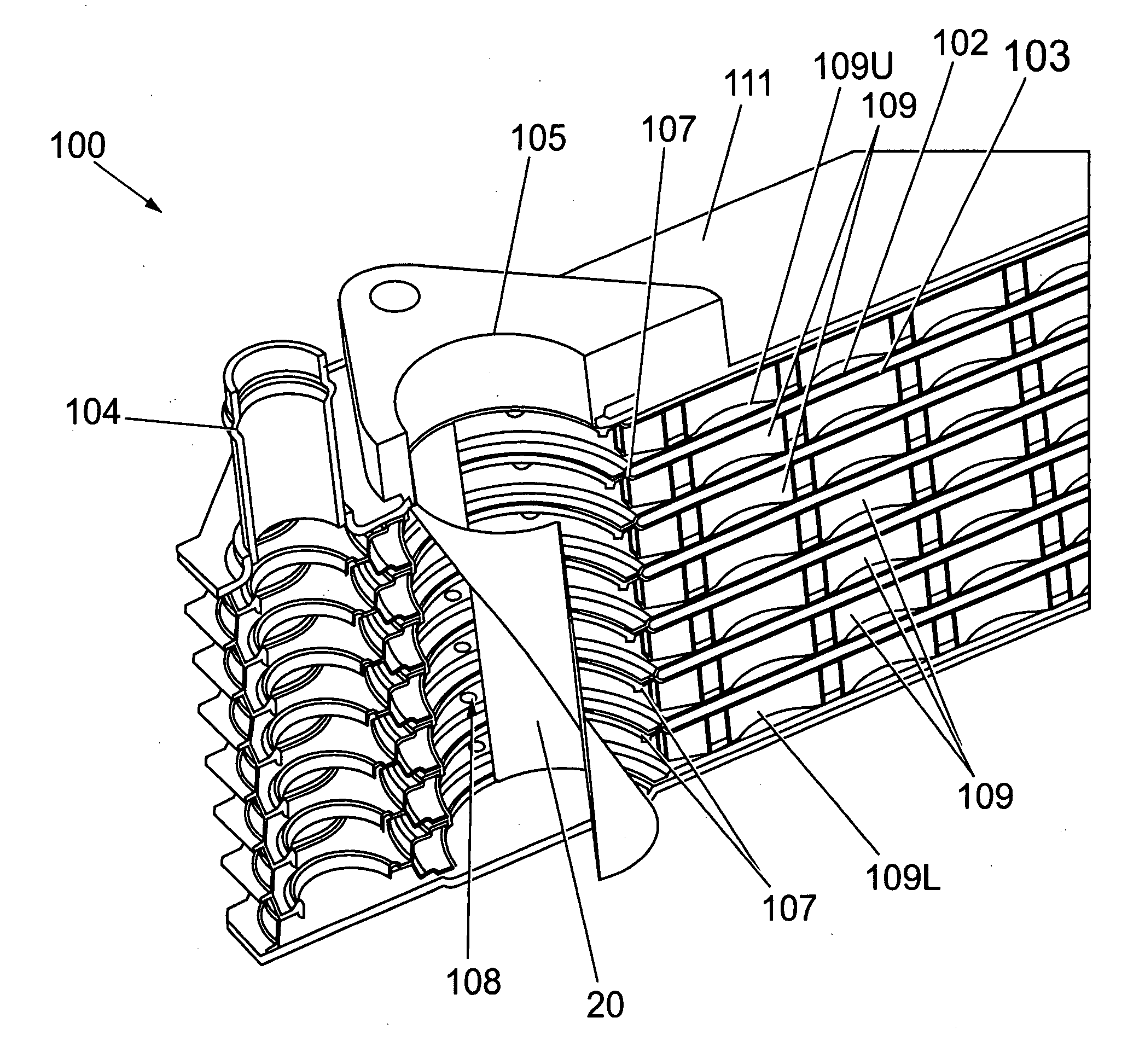
[0088] A further embodiment 40 is shown in FIG. 6. The deflector 40 comprises a half-cylinder 42 cut at an angle to form a part-cylinder 42 with an upper end having a larger edge than its lower end. This results in a concave portion with, looking down its main axis, a C-shaped profile. The profile of the part-cylinder gradually reduces towards its opposite end due to the angled cut. In place of the deflector 20, the deflector 40 is provided in the manifold hole 108 of the exhaust gas cooler 100 at an angle between that of the direction of exhaust gas flow from the exhaust gas inlet 105 and the direction of exhaust gas flow of the exhaust gas through the exhaust gas passages 109. This progressively reduces the flow area towards the lower end of the manifold hole 108 thus restricting exhaust gas flow to the lower exhaust gas passages 109. This restriction, in use, also serves to redress the imbalance in exhaust gas flow between the various exhaust gas passages by restricting exhaust g...

embodiment 50

[0096]FIG. 7 shows a simplified view of a further embodiment 50 of the present invention. An exhaust gas cooler 200 is shown comprising an exhaust gas inlet 205 and exhaust gas passages 209 and an inlet chamber 208 defined by apertures 207 in plate pairs 202. Coolant passages and a coolant inlet are provided but are omitted from FIG. 7 for clarity.

[0097] The apertures 207 of the plate pairs decrease in size in order to restrict flow of exhaust gas to the lower passages. Preferably two or three plate pairs are provided with an equal size of apertures in order to simplify assembly.

[0098] Thus in use, exhaust gas proceeds through the exhaust gas inlet 205. The flow area of the inlet chamber 208 gradually reduces in size which restricts flow to the lower exhaust gas passages 209 and encourages the exhaust gas to proceed through the upper exhaust gas passages 209.

[0099] This embodiment also serves to reduce the imbalance between the amount of flow through the various exhaust gas passag...


PUM


Abstract

An exhaust gas cooler comprising an inlet chamber shaped to restrict exhaust gas flow to certain exhaust gas passages provided therein is disclosed. The inlet chamber may comprise a flow deflector which deflects a proportion of exhaust gas into, for example, the upper exhaust gas cooling passages thus restricting flow to lower exhaust gas cooling passages. In one embodiment the flow deflector is rotatably mounted and can also function as a bypass valve. Alternatively apertures provided within plates which can collectively define the inlet chamber may be of a differing size to restrict exhaust gas flow to certain exhaust gas cooling passages. A more balanced flow through the various exhaust gas cooling passages results increasing heat-exchange efficiency of the exhaust gas cooler.

Description

BACKGROUND OF THE INVENTION [0001] 1. Field of the Invention [0002] The present invention relates to an exhaust gas cooler, in particular an exhaust gas recirculation (EGR) cooler. [0003] 2. Description of the Related Art [0004] Emissions regulations are requiring reduced emissions from vehicles, particularly the Euro 5, Bin 5 and US 07 regulations. To reduce the generation of nitrous oxides, it is known to recirculate exhaust gas through the engine. Under normal conditions the exhaust gas must be cooled before recirculation and it is known to pass the exhaust gas through an exhaust gas cooler. The exhaust gas cooler transfers heat between exhaust gas passages and liquid cooled passages in order to cool the exhaust gas before it is re-circulated into engine intake. Under “cold start” or other low operating conditions, the gas can be over-cooled resulting in increased hydrocarbon emission and CO2 production. [0005] A bypass around the exhaust gas cooler may be provided to allow the e...

Claims


Application Information

Patent Timeline
Patent Type & Authority Applications(United States)
IPC IPC(8): F01N3/02F02M25/07
CPCF01N2240/02F01N2240/20F01N2260/024F02M25/0729F02M25/0737F28D9/005F28D21/0003F28F9/0265Y02T10/121F02M26/26F02M26/32
Inventor DILLEY, ROLAND L.BELDAM, RICHARD P.AGEE, KEITH D.MAGALHAES, WAGNER M.
Owner HONEYWELL INT INC
Why Eureka
Try Eureka