Braceless liner

a technology of liner and brace, which is applied in the field of liner system, can solve the problems of affecting the quality of the liner, the sensitivity of the conventional liner to tears or ruptures, and the sliding action placing great stress on the various points of the conventional liner, so as to achieve the effect of simple and economical manufacture, assembly and us

Inactive Publication Date: 2006-08-10
POWETEX
View PDF80 Cites 14 Cited by
  • Summary
  • Abstract
  • Description
  • Claims
  • Application Information

AI Technical Summary

Benefits of technology

[0007] The present invention is directed to a shipping container liner or bulkhead liner for a cargo carrier that resists shear, expansion, and gravitational forces imparted by a cargo or product held in the bulkhead liner. The component parts of the bulkhead liner are simple and economical to manufacture, assemble and use. Other advantages of the invention will be apparent from the following description and the attached drawings, or can be learned through practice of the invention.
[0018] A lattice is attached to the exterior surface in this aspect. The lattice includes a number of straps with at least one upper support strap and at least one lower support strap to counteract an expansion force exerted by the product in the cavity. At least one sheath is affixed to the interior surface of the bulkhead liner, and at least one load-bearing band is contained in the sheath such that the load-bearing band is separate from the product. The sheath and the load-bearing band are not attached to each other so that when the expansion force is imparted by the product, the sheath and the load-bearing band do not tear apart and contaminate the product as the load-bearing band, which is attached to a portion of the lattice, further counteracts the expansion force exerted by the product in the cavity.
[0019] The straps are attached to the exterior surface near the door. The straps and the load-bearing band thus prevent the exterior surface from contacting the door when the bulkhead liner is filled with the product.
[0020] Also in this aspect, the sheath is sealed to the interior surface at an intersection point with the load-bearing band. Alternatively, the sheath is sealed between the exterior and interior surfaces. The sheath extends away from the interior surface through the exterior surface. The sheath has a termination opening through which the load-bearing band extends for attachment of the load-bearing band to a tie-down in the container. In this aspect of the invention, respective termination openings of the sheaths are spaced ten to fifteen inches from respective tie-downs in the container. This arrangement prevents the liner from shifting out of the container.
[0024] The method also includes the step of loading a product into the cavity via the loading aperture. As the product is loaded, the lattice and the load-bearing band resist an expansion force exerted by the product in the cavity. As noted above, the load-bearing band should be movable in the sheath to prevent damage to the sheath and the pliable body and contamination to the product.

Problems solved by technology

The conventional liner is extremely susceptible to tears or ruptures under certain conditions.
This sliding action places great stress on various points of the conventional liner.
This stress can cause the liner to rupture, which results in spillage and contamination of the cargo.
Additionally, the shifting cargo can cause the liner itself to slide through the rear door of the container and rupture over an edge of the cargo container or upon impact with the ground.
However, the braces are cumbersome, bulky and can interfere with unloading the cargo.
The braces ironically can damage the liner they are intended to protect as the discharging cargo presses the liner against the braces.

Method used


Image

  • Braceless liner
  • Braceless liner
  • Braceless liner

Examples


Embodiment Construction

[0035] Detailed reference will now be made to the drawings in which examples embodying the present invention are shown. The detailed description uses numerical and letter designations to refer to features of the drawings. Like or similar designations of the drawings and description have been used to refer to like or similar parts of the invention.

[0036] The drawings and detailed description provide a full and written description of the invention, and of the manner and process of making and using it, so as to enable one skilled in the pertinent art to make and use it, as well as the best mode of carrying out the invention. However, the examples set forth in the drawings and detailed description are provided by way of explanation only and are not meant as limitations of the invention. The present invention thus includes any modifications and variations of the following examples as come within the scope of the appended claims and their equivalents.

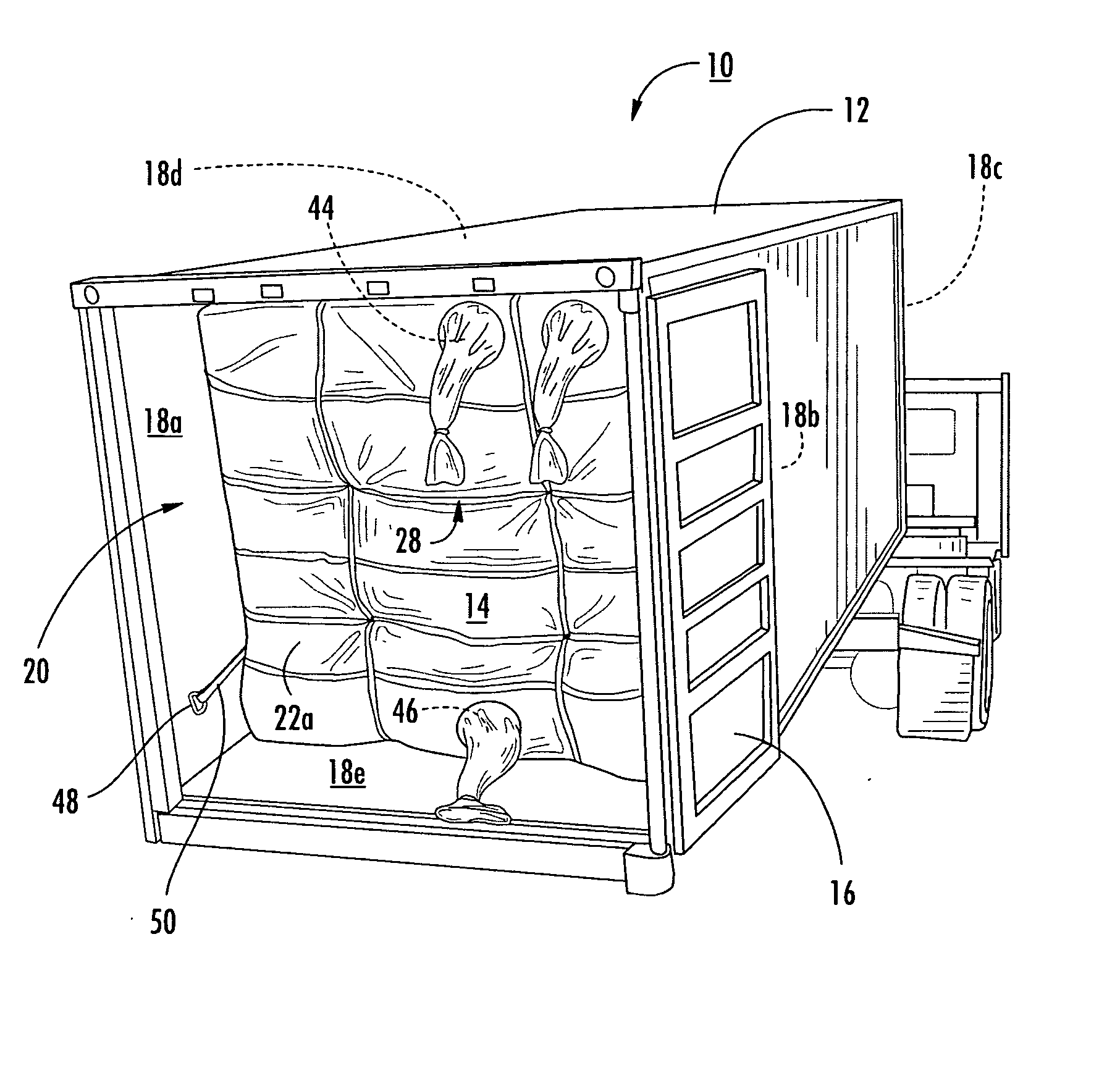
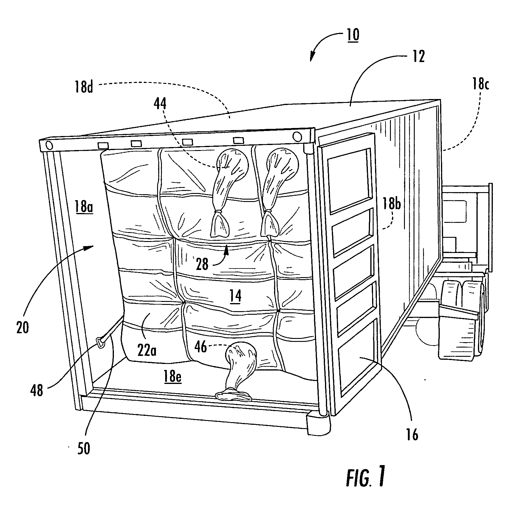
[0037] A container system is broadly...


PUM


Abstract

A container system having a bulkhead liner and method of using the bulkhead liner includes a pliable body with an exterior surface and an interior surface forming a cavity therein. At least one loading aperture is formed through the exterior and interior surfaces for loading a product in the cavity. When filled with the product, the pliable body substantially assumes a shape complementary to the shipping container shape. In one aspect of the invention, a lattice having a plurality of straps is affixed to the exterior surface to resist an expansion force exerted by the product from within the cavity. At least one load-bearing band is situated within the cavity of the pliable body shrouded by a sheath to protect the product from contamination by external elements to which the load-bearing band may be exposed. The load-bearing band is freely movable within the sheath to prevent damage to the pliable body when the product fills the cavity and imparts an expansion force against the pliable body. The load-bearing band is attached to a portion of the lattice to provide additional resistance against the expansion force exerted by the product in the cavity.

Description

FIELD OF THE INVENTION [0001] This invention relates to a liner system for a shipping container. BACKGROUND OF THE INVENTION [0002] Cargo containers are used to carry bulk cargo such as dry bulk chemicals, powdered and pelletized resins, flour, coffee, grains and the like. When cargo containers are used to carry bulk cargo, the container must be kept clean or be cleaned after each load of cargo is emptied from the container, so that the container can be subsequently used with another load of cargo. Moreover, the cargo must be protected from contamination and from undesirable exposure to natural elements. [0003] Removable liners typically are used to line interior walls or surfaces of the cargo containers in order to carry the bulk cargo without sullying the container and contaminating the cargo. Such a liner protects the cargo during shipment or storage from rain, debris, and the like. After the cargo is delivered, the liner can be removed so that the container is again useable with...

Claims


Application Information

Patent Timeline
Patent Type & Authority Applications(United States)
IPC IPC(8): B65D88/00
CPCB65D90/046B65D90/048B65D2590/046
Inventor PODD, STEPHEN D.
Owner POWETEX
Why Eureka
Try Eureka