
Combustion-engined setting tool

a technology of combustion engine and setting tool, which is applied in the direction of stapling tools, manufacturing tools, nailing tools, etc., can solve the problems of large weight, large diameter of combustion chamber, complicated drawback of known setting tool, etc., and achieve the effect of reliable cable drive operation

Active Publication Date: 2006-08-10
HILTI AG
View PDF19 Cites 13 Cited by
  • Summary
  • Abstract
  • Description
  • Claims
  • Application Information

AI Technical Summary

Benefits of technology

[0017] With the cable drive according to the invention, the press-on stroke can be transmitted to the combustion chamber for expanding the same in a simple manner, which permits to obtain a short ergonomical press-on stroke with the use of a small number of additional parts, low assembly costs, and a small diameter of the combustion chamber. When, e.g., a single deflection roller is available then the transmission ratio between the press-on stroke and the resulting expansion movement of the combustion chamber sleeve is 1:2. The advantage of the cable drive further consists in that it is less expensive and has a smaller weight in comparison with toothed gear or rack-and-pinion gear.
[0019] Advantageously, the at least one second roller for the transmission member is supported on the guide cylinder which permits to simplify the construction and to provide a preliminary formed assembly of guide cylinder, combustion chamber sleeve, bolt guide, and cable drive and which can easily be mounted in a setting tool housing.
[0021] With this embodiment of the setting tool, in addition to the deflection roller supported on the press-on element no further deflection roller is needed, which simplifies manufacturing of the setting tool.
[0026] Advantageously, the cable drive has two separate transmission members arranged symmetrically, and at least one first deflection roller for each transmission element and which is provided on the press-on element. With two transmission members, a uniform distribution of forces during the press-on and lift-off step can be achieved, which eliminates the possibility that parts, which move relatively to each other, would tilt toward each other.

Problems solved by technology

The drawback of the known setting tool is a complicated and expensive to produce, mechanics that provides for expansion of the combustion volume in the combustion chamber.
However, the above-described setting tool has a relatively long press-on path and a relatively large diameter of the combustion chamber.
The drawback of this setting tool consists in its large weight resulted from need in battery or accumulator and in need to replace them when their energy dies out.

Method used


Image

  • Combustion-engined setting tool
  • Combustion-engined setting tool
  • Combustion-engined setting tool

Examples


Embodiment Construction

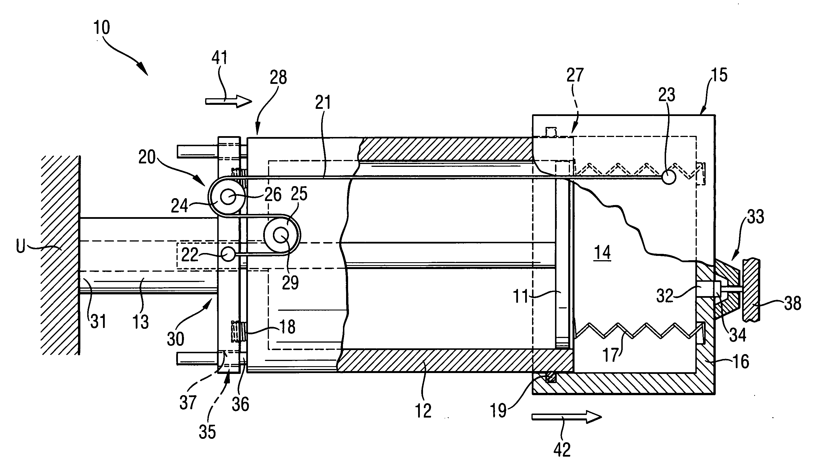
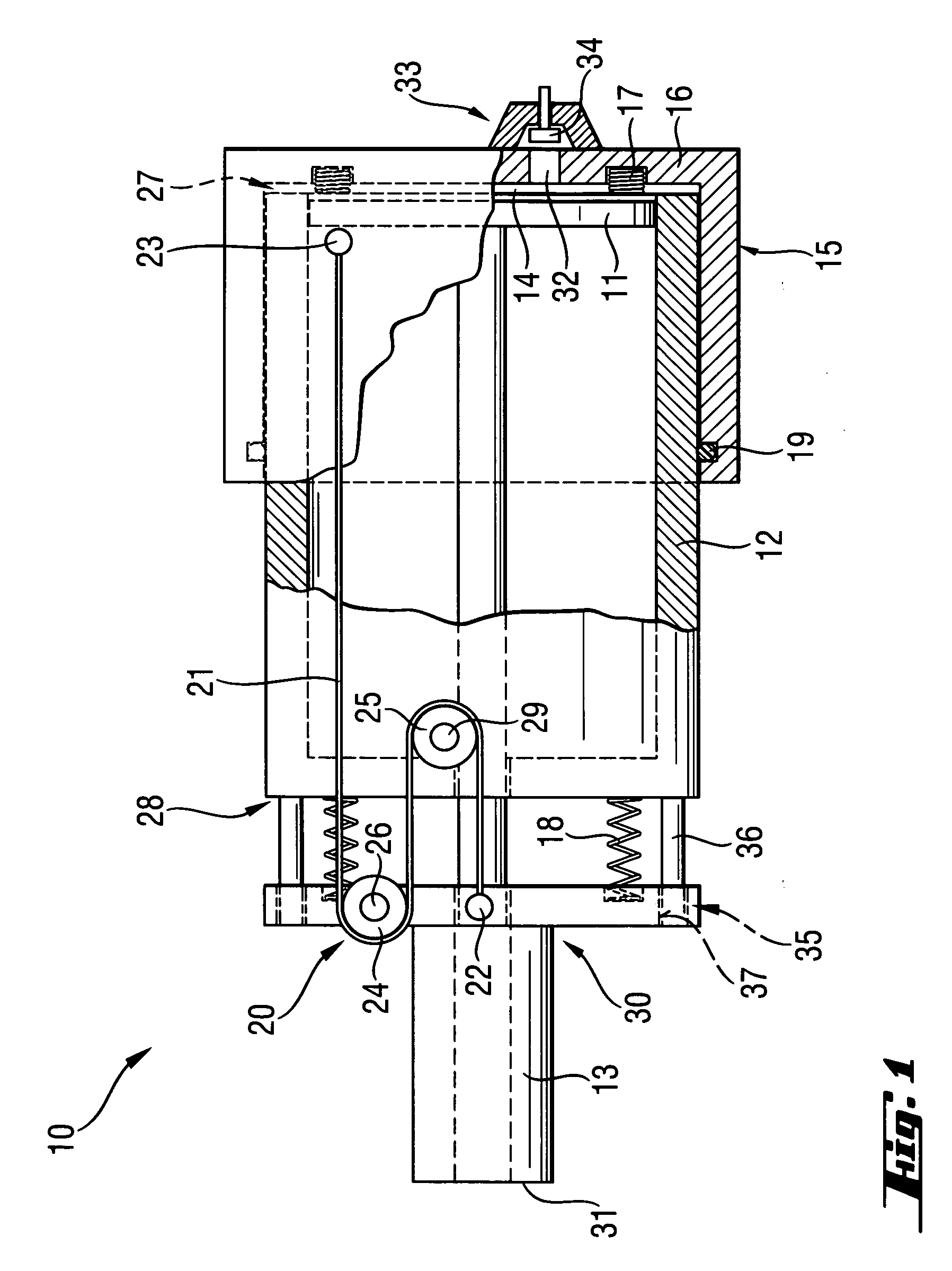
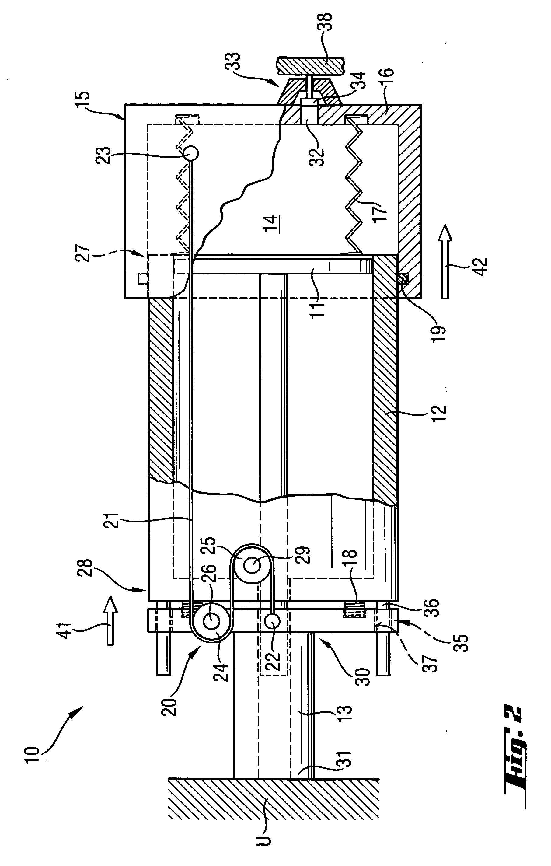
[0034]FIGS. 1-2 show a first embodiment of a setting tool according to the present invention. The setting tool 10 is operated on a fuel gas which is stored in a fuel reservoir (not shown) in form of a liquefied gas. Instead of a fuel gas, an evaporable liquid fuel such as, e.g., alcohol, gasoline can be used. The setting tool 10 has a setting mechanism with which a fastening element, not shown, is driven in a constructional component U when the setting tool 10 is pressed against the construction component and is actuated. The setting mechanism includes, among others, a combustion chamber 14 for an oxidant-fuel gas mixture, a guide cylinder 12 having a first axial end 27 and a second axial end 28, a setting piston 11 axially displaceable in the guide cylinder 12, and a bolt guide 13 adjoining the second axial end 28 of the guide cylinder 12 remote from the combustion chamber 14. The bolt guide 13 serves for guiding a fastening element, e.g., a bolt or a nail, functioning simultaneous...


PUM

PropertyMeasurementUnit
spring forceaaaaaaaaaa
setting energyaaaaaaaaaa
pressureaaaaaaaaaa

Abstract

A combustion-engined setting tool for driving fastening elements in a constructional component, includes a guide cylinder (12), a setting piston (11) displaceable in the guide cylinder (12), a combustion chamber sleeve (15) displaceably arranged at the first axial end (27) of the guide cylinder (12), a press-on element (30) supported at the second axial end (28) of the guide cylinder (12), and a transmission device for connecting the press-on element (30) with the combustion chamber sleeve (15) and formed as a cable drive (20) having a transmission member (21, 121) and at least one deflection roller (24, 124) for the transmission member (21, 121) and supported on the press-on element (30).

Description

BACKGROUND OF THE INVENTION [0001] 1. Field of the Invention [0002] The present invention relates to a combustion-engined setting tool for driving fastening elements in a constructional component and including a guide cylinder having opposite first and second axial ends, a setting piston displaceable in the guide cylinder, a combustion chamber sleeve displaceably arranged at the first axial end of the guide cylinder, a press-on element supported at the second axial end of the guide cylinder for displacement relative thereto, and a transmission device for connecting the press-on element with the combustion chamber sleeve for converting a press-on displacement of the press-on element into displacement of the combustion chamber sleeve. [0003] 2. Description of the Prior Art [0004] Setting tools of the type described above are operated with gaseous or liquid fuels that should be evaporated before combustion. The setting energy for driving in a fastening element is produced by combustion...

Claims


Application Information

Patent Timeline
Patent Type & Authority Applications(United States)
IPC IPC(8): B25C1/14
CPCB25C1/08B25C1/14
Inventor ZAHNER, MARIOROSENBAUM, ULRICHTILLE, DIERK
Owner HILTI AG
Features
  • Generate Ideas
  • Intellectual Property
  • Life Sciences
  • Materials
  • Tech Scout
  • Unparalleled Data Quality
  • Higher Quality Content
  • 60% Fewer Hallucinations
Learn More