Code reader

Active Publication Date: 2006-08-10
SICK AG
View PDF32 Cites 23 Cited by
  • Summary
  • Abstract
  • Description
  • Claims
  • Application Information

AI Technical Summary

Benefits of technology

[0007] It is an object of the invention to further develop a code reader of the initially named kind such that it is also suitable for the reading of DPM codes without

Problems solved by technology

The reading of DPM codes is difficult when the code reader is arranged perpendicular above the code, since the light source integrated in the code reader then illuminates the code at an angle of incidence which coincides at least largely with the optical axis of the code reader, which has the consequence that no great contrast difference occurs between the regions of the carrier

Method used


Image

  • Code reader
  • Code reader
  • Code reader

Examples


Embodiment Construction

[0033] The following description of the preferred embodiments is merely exemplary in nature and is in no way intended to limit the invention, its application, or uses.

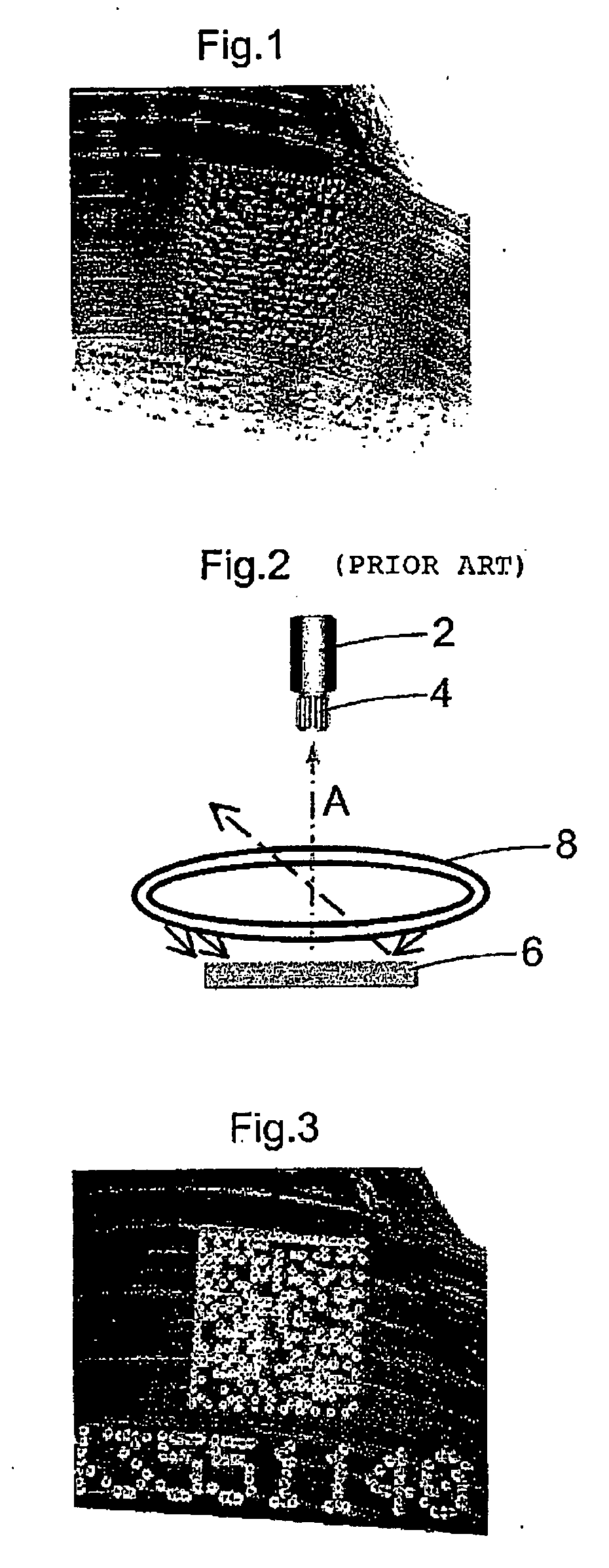
[0034] The code shown in FIG. 1 was introduced into a metal carrier by means of dot peening and consists of a square field of indentations arranged in a predetermined pattern, with each indentation having been produced by a needle impressed into the metal carrier. An arrangement of a plurality of numbers, likewise formed from individual indentations, are located beneath the square field.

[0035] The code in accordance with FIG. 1 cannot be recognized very easily since it was taken by a code reader with frontal illumination that is with a direction of illumination extending perpendicular to the carrier material.

[0036]FIG. 2 shows a schematic representation of an arrangement in accordance with the prior art which is suitable for an improved reading of DPM codes, that is, for example, also of a code in accordance with FI...


PUM


Abstract

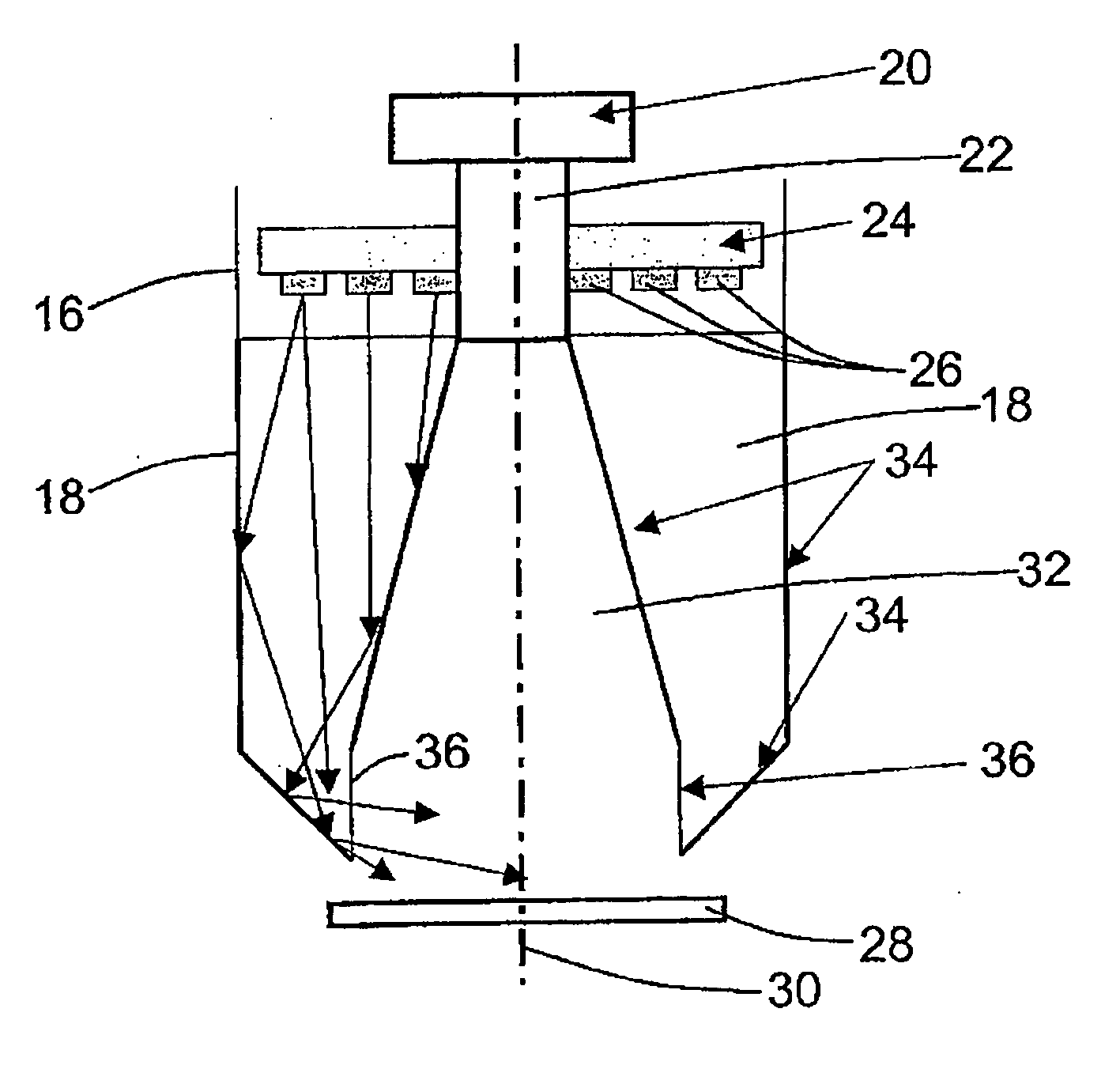
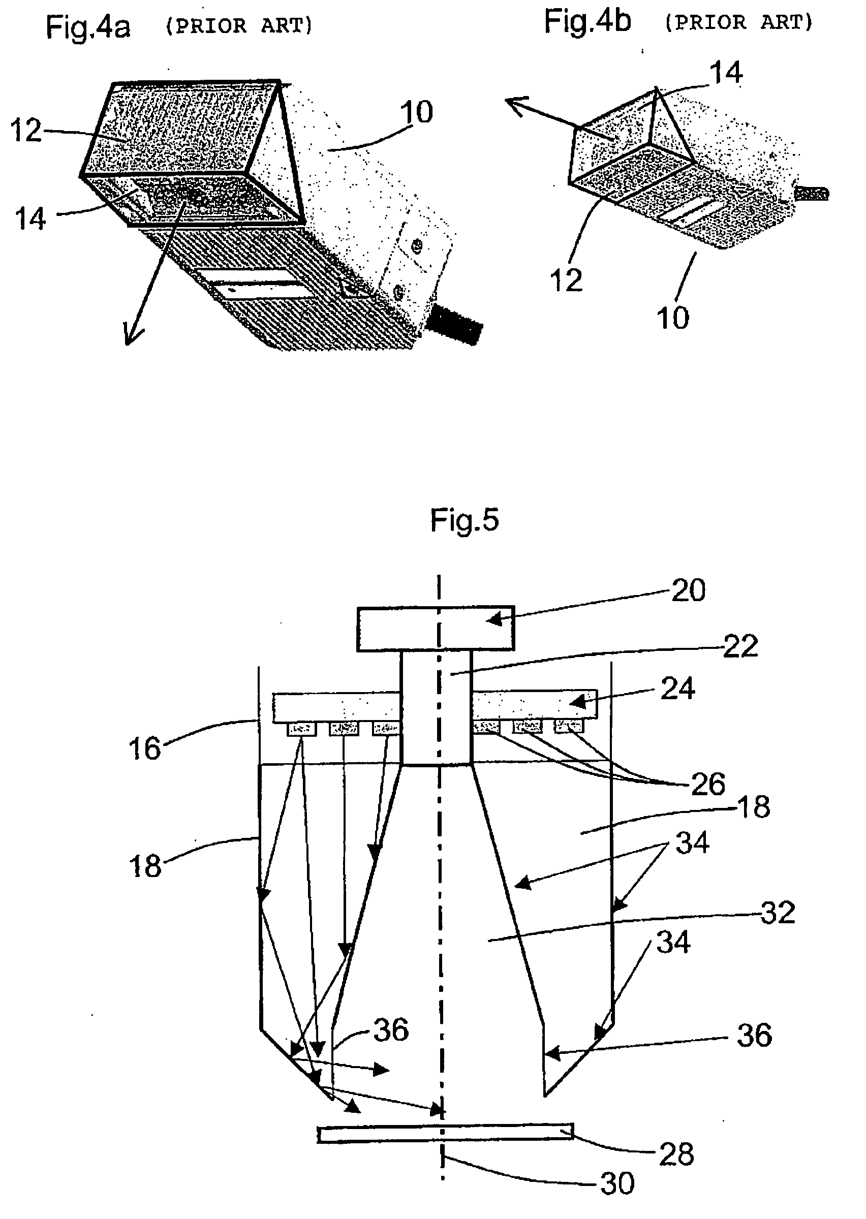
A code reader comprising an integrated light source for the illumination of a reading region, a sensor matrix and an optical receiving system positioned in front of the latter, wherein the light emergence surface of the light source is located in or closely in front of the depth of field zone of the optical receiving system.

Description

CROSS-REFERENCE TO RELATED APPLICATIONS [0001] This application claims the benefit of German Patent Application No. 10 2005 005 536.2, filed on Feb. 7, 2005. The disclosure of the above application is incorporated herein by reference. FIELD AND BACKGROUND OF THE INVENTION [0002] The invention relates to a code reader having an integrated light source for the illumination of a reading zone and having a sensor matrix and an optical receiving system positioned in front of said sensor matrix. [0003] Code readers are known in a variety of embodiments from the prior art and are also used inter alia to read codes which were applied directly to the respective carrier material by a deformation thereof. Codes of this type, which are known, for example, as so-called DPM codes (direct part marking codes), are generated, for example, in that the carrier material is acted on by a high-energy laser or by means of pin stamping (“dot peening”). It is common to both methods that recesses or indentati...

Claims


Application Information

Patent Timeline
IPC IPC(8): G06K7/10
CPCG06K7/10544G06K7/10732
Inventor REICHENBACH, JURGENRUNGE, WOLFRAMWEBER, HELMUT
Owner SICK AG
Why Eureka
Try Eureka