Fuel injection valve

a fuel injection valve and valve body technology, applied in the direction of fuel injection apparatus, fuel feed system, engine components, etc., can solve the problems of increasing installation space, bulky valve housing, and making both longer

Inactive Publication Date: 2006-08-10
ROBERT BOSCH GMBH
View PDF3 Cites 7 Cited by
  • Summary
  • Abstract
  • Description
  • Claims
  • Application Information

AI Technical Summary

Benefits of technology

[0007] In an advantageous manner, the coupler acts on the valve needle via a calotte, so that offsets are able to be compensated.

Problems solved by technology

Disadvantageous in the metering valve described in German Patent Application No.
Furthermore, the lines have to be installed around the coupler, which makes them both longer and also increases the installation space.
The valve housing becomes bulky as a result and in turn requires larger installation space in the cylinder head.

Method used


Image

  • Fuel injection valve
  • Fuel injection valve
  • Fuel injection valve

Examples


Embodiment Construction

[0012] In the following, a preferred exemplary embodiment of the present invention is described by way of example. In this context, corresponding components are provided with the same reference numerals in all of the figures.

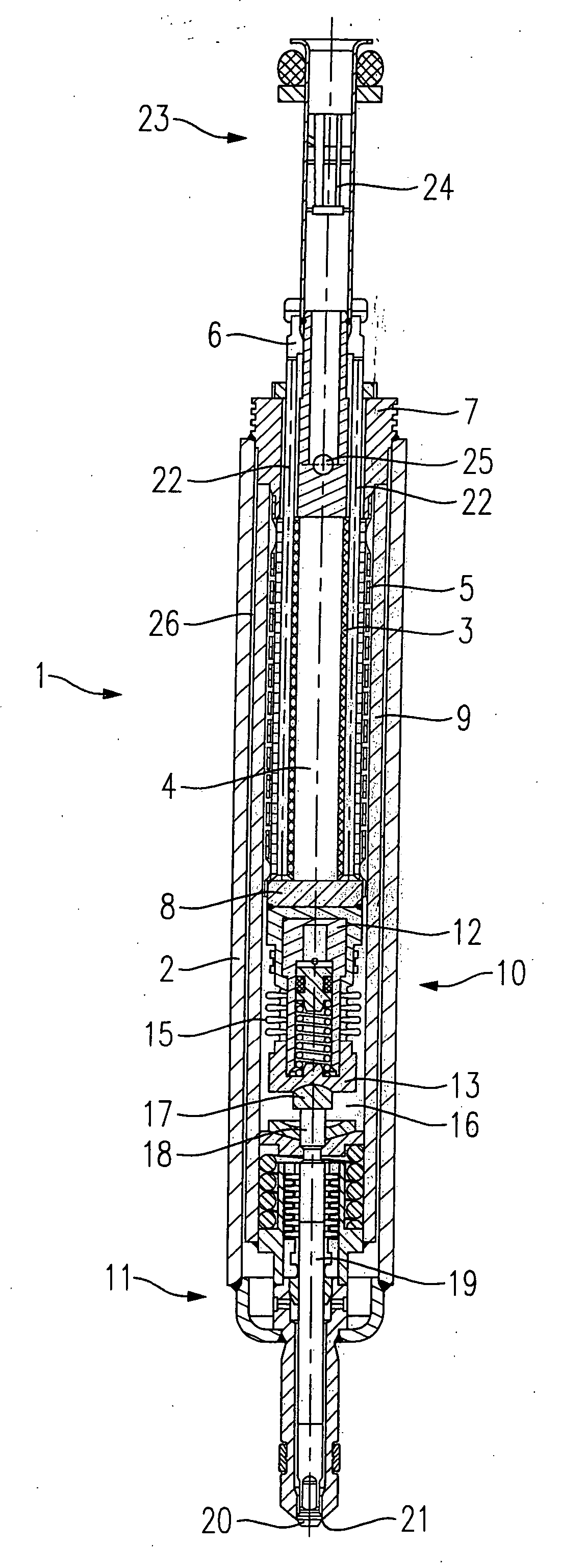
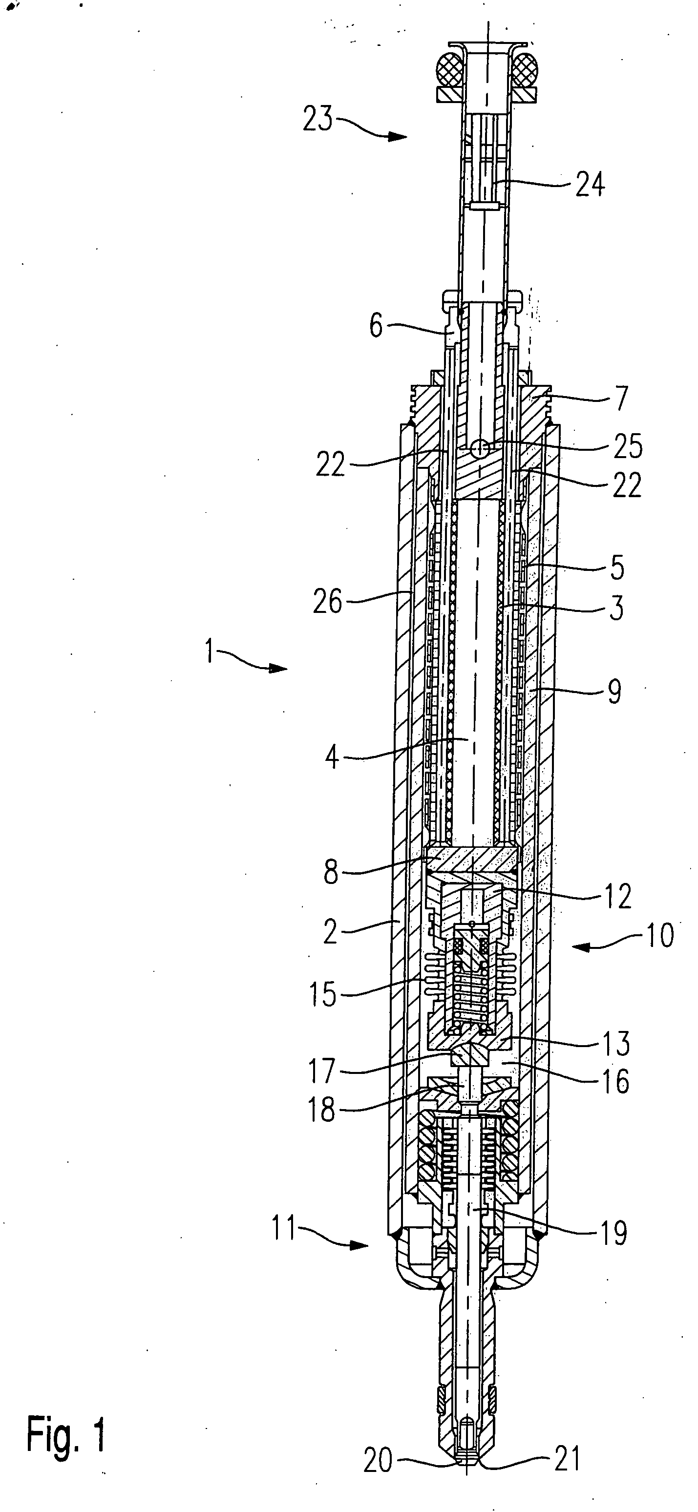
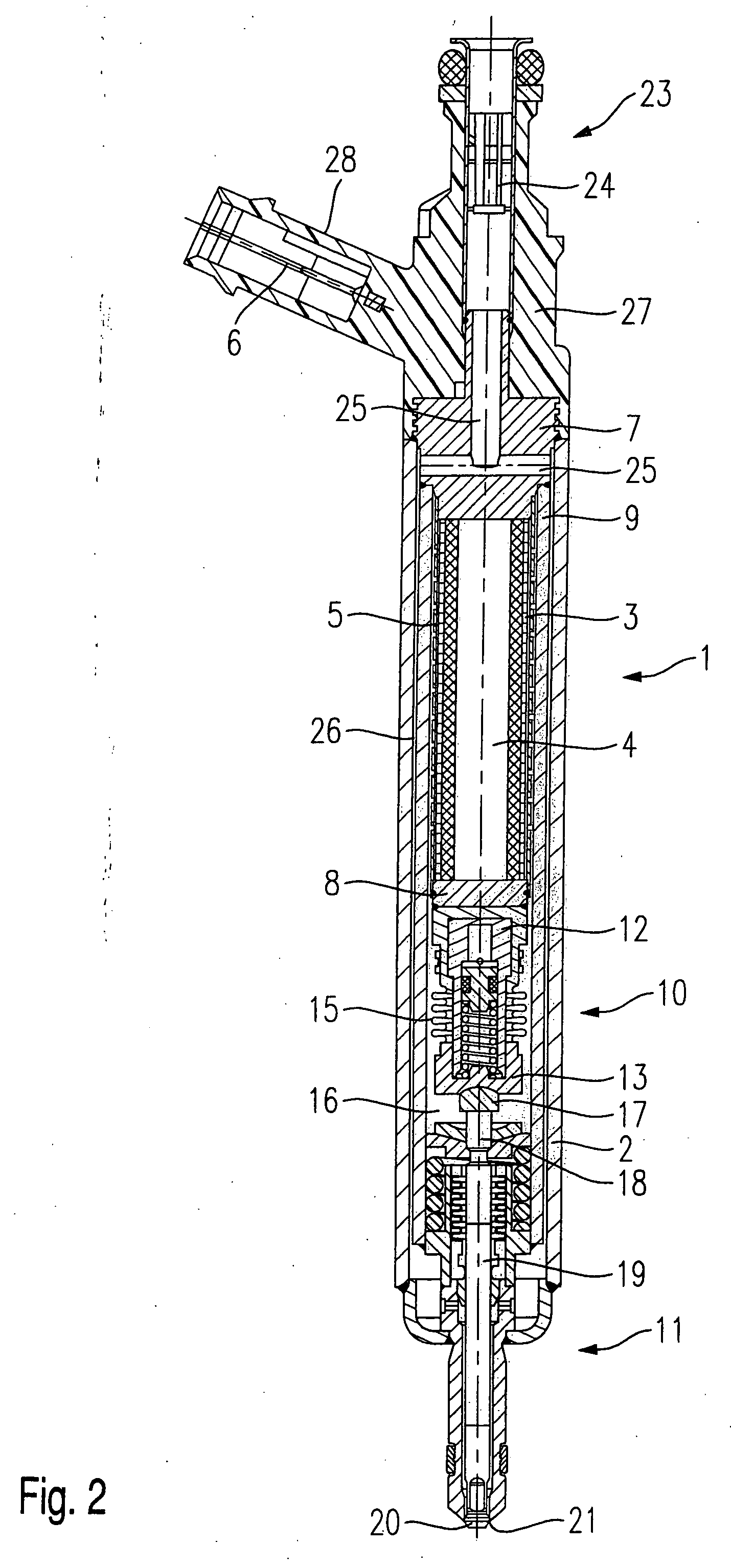
[0013] A fuel injector 1 shown in FIGS. 1 and 2 in two mutually perpendicular sectional views along a longitudinal axis is designed in the form of a fuel injector 1 for fuel-injection systems of mixture-compressing internal combustion engines having externally supplied ignition. Fuel injector 1 is particularly suited for the direct injection of fuel into a combustion chamber (not shown) of an internal combustion engine.

[0014] Fuel injector 1 includes a housing 2 in which a piezoelectric or magnetostrictive actuator 4 provided with an actuator extrusion coat 3 is arranged. Actuator 4 is prestressed by a tubular spring 5 to allow a non-destructive installation and a reproducible actuation of actuator 4. An electrical voltage may be supplied to actuator 4 via an ...


PUM


Abstract

A fuel injector, in particular a fuel injector for fuel-injection systems of internal combustion engines, includes a piezoelectric or magnetostrictive actuator which is excitable via an electrical line and actuates a valve-closure member arranged in a housing, the valve-closure member cooperating with a valve-seat surface to form a sealing seat, and an hydraulic coupler. The hydraulic coupler is fixedly arranged between the actuator and a valve-assembly that includes the valve-closure member and the valve-seat surface.

Description

BACKGROUND INFORMATION [0001] German Patent Application No. DE 35 33 085 describes a metering valve for the metering of fluids or gases, especially an injection valve for fuel-injection systems in internal combustion engines, which includes a piezo stack actuator whose linear deformation in response to the application of an excitation voltage is transmitted to a valve needle which controls a metering orifice and determines the valve lift of the valve needle. The substance to be metered is supplied via a supply line which is designed in the form of a deep-hole bore in the valve body. [0002] Disadvantageous in the metering valve described in German Patent Application No. DE 35 33 085 is the floating suspension of the hydraulic coupler between fuel intake and actuator, which exposes the coupler to fluctuations in the fuel pressure. The electrical lines required for the contacting of the actuator must be run in a complicated manner to prevent tensile stressing due to the positional chan...

Claims


Application Information

Patent Timeline
Patent Type & Authority Applications(United States)
IPC IPC(8): B05B1/30F02M51/00F02M51/06F02M61/08F02M61/16F02M63/00
CPCF02M51/005F02M51/0603F02M61/08F02M61/167F02M2200/703
Inventor STIER, HUBERT
Owner ROBERT BOSCH GMBH
Why Eureka
Try Eureka