
Multichannel array waveguide diffraction grating multiplexer/demultiplexer and method of connecting array waveguide and output waveguide

a multi-channel array and array waveguide technology, applied in the field of optical multiplexers/demultiplexers, can solve the problems of increasing the pass bandwidth and ripping, and achieve the effect of reducing connection loss and small loss

Inactive Publication Date: 2006-08-10
ORMON CORP
View PDF3 Cites 37 Cited by
  • Summary
  • Abstract
  • Description
  • Claims
  • Application Information

AI Technical Summary

Benefits of technology

[0014] It is an object of the present invention to decrease connection loss caused by a mismatched mode between a second slab waveguide and an output waveguide in an array waveguide diffraction grating (AWG) multiplexer / demultiplexer, and to obtain composing / decomposing characteristics with a small loss.
[0020] Namely, in the above-mentioned multichannel array waveguide diffraction grating multiplexer / demultiplexer, the output waveguide is given a predetermined form, which is changed to meet the form of field distribution at a light collecting point in the output slab waveguide, and connected to the output slab waveguide. Thus, connection loss is decreased, and asymmetry of transmission characteristics is decreased.
[0025] Namely, in the above multichannel array waveguide diffraction grating multiplexer / demultiplexer, assuming that an angle formed between a normal line of the Rowland circle and a center line of the cores placed on both sides of a center core is α, spell an angle between a normal line of the Rowland circle and a center line of the core, the cores provided for a desired number of channels are connected to the output side slab waveguide at an angle defined by α, 2α, 3α, . . . , (N−1)α, Nα, from the center core to the cores on both sides, according to the position from the center core. The field distribution at the light collecting point of the slab waveguide becomes identical to the field distribution of the output waveguide. Therefore, the connection loss is decreased, and the evenness of the outputs of each channel is increased when a multichannel light wave is divided.
[0027] Namely, in the above connection method, a desired number of output waveguides is provided for multichannel and the cores changed to meet the field distribution at a light collecting point of the slab waveguide at an angle defined by α, 2α, 3α, . . . , (N−1)α, Nα, from the center core on the circumference of Rowland circle to the cores on both sides according to the position from the center core on the circumference of the Rowland circle. Thereby, connection loss is decreased, and evenness of the outputs of each channel is increased.

Problems solved by technology

Further, in an array waveguide with flat top transmission characteristics, ripple in the pass bandwidth increases.

Method used


Image

  • Multichannel array waveguide diffraction grating multiplexer/demultiplexer and method of connecting array waveguide and output waveguide
  • Multichannel array waveguide diffraction grating multiplexer/demultiplexer and method of connecting array waveguide and output waveguide
  • Multichannel array waveguide diffraction grating multiplexer/demultiplexer and method of connecting array waveguide and output waveguide

Examples


Embodiment Construction

[0036] Embodiments of the present invention will be explained in detail hereinafter with reference to the accompanying drawings.

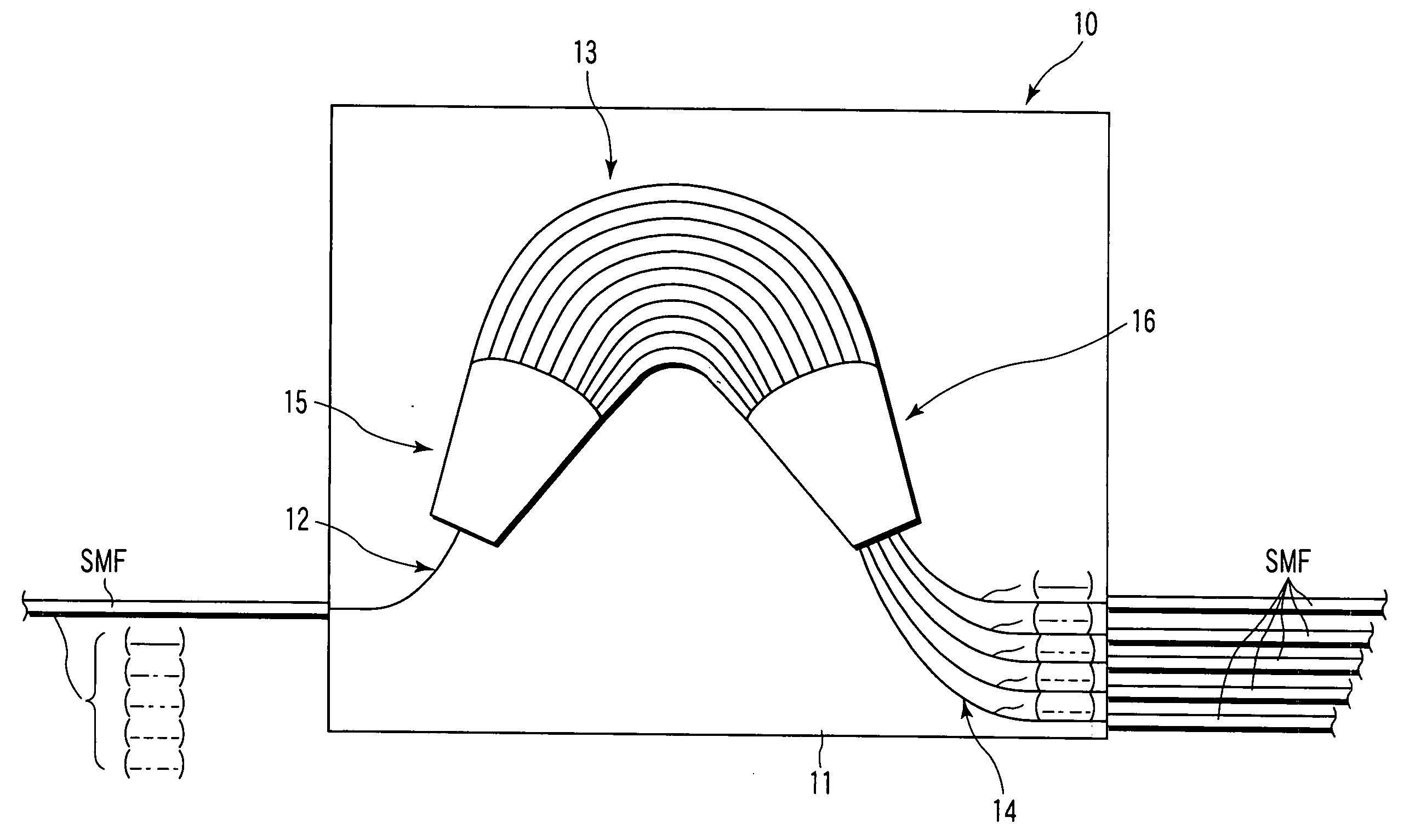
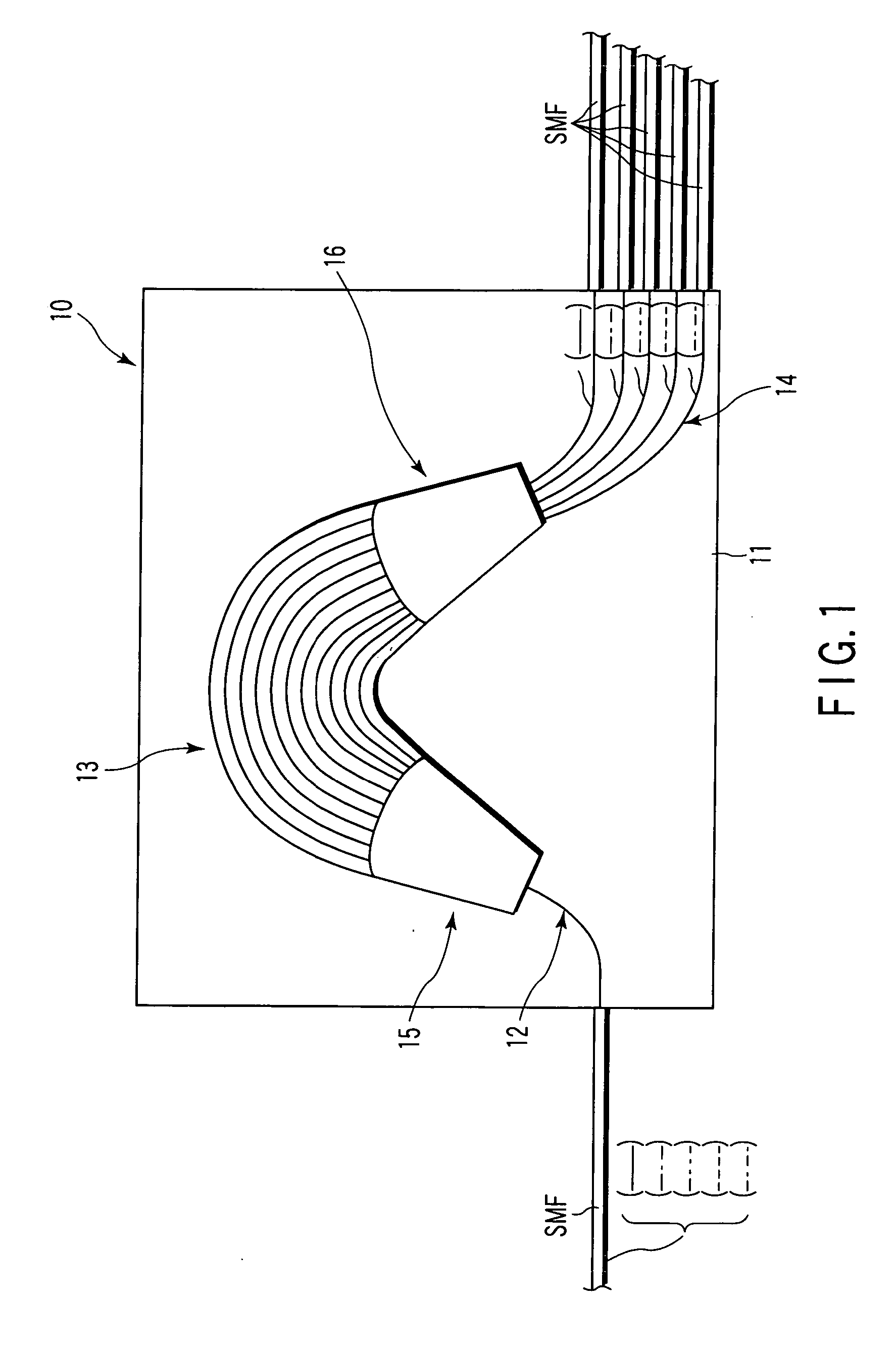
[0037] As shown in FIG. 1, an array waveguide optical multiplexer / demultiplexer 10 has an input waveguide 12, array waveguide 13 and output waveguide 14 provided at predetermined positions on a base board 11, and first and second slab waveguides 15 and 16 each optically connect the input waveguide 12 and the array waveguide 13 and the array waveguide 13 and the output waveguide 14.

[0038] The array waveguide 13 is formed with a predetermined curvature between the first and second slab waveguides 15 and 16.

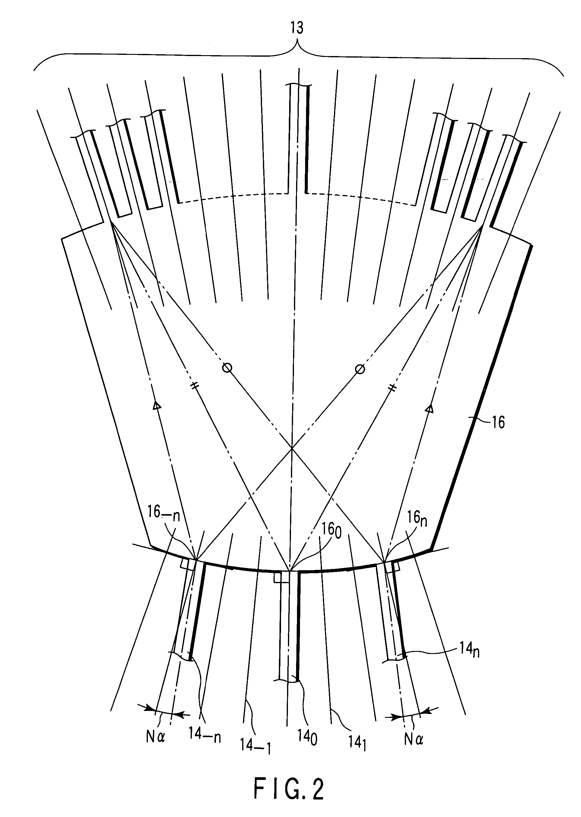
[0039] As shown in FIG. 2, cores 14−n to 14n except a core 14o of the output waveguide 14 are connected to output ports 16−n and 16n of the second slab waveguide 16 at a desired position on the circumference of the Rowland circle defining the output terminal of the second waveguide 16 in the state that the center axis is inclined by a predetermined angle...


PUM


Abstract

An array waveguide diffraction grating optical multiplexer / demultiplexer having an input waveguide, an input side slab waveguide, an output side slab waveguide, an output waveguide, an array waveguide provided between the input side slab waveguide and output side slab waveguide having a length different sequentially between the adjacent waveguides, wherein the output waveguide is arranged so that the angle formed between each output waveguide and the normal line of the Rowland circle of the output waveguide is sequentially increased from the central output waveguide to the output waveguide at both ends of the central output waveguide, and asymmetry of the passband of the output waveguide based on the form of field distribution at a light collecting point of the output side slab waveguide is decreased.

Description

CROSS-REFERENCE TO RELATED APPLICATIONS [0001] This is a Continuation Application of PCT Application No. PCT / JP2004 / 017625, filed Nov. 26, 2004, which was published under PCT Article 21(2) in Japanese. [0002] This application is based upon and claims the benefit of priority from prior Japanese Patent Applications No. 2003-400839, filed Nov. 28, 2003; and No. 2004-342787, filed Nov. 26, 2004, the entire contents of both of which are incorporated herein by reference.BACKGROUND OF THE INVENTION [0003] 1. Field of the Invention [0004] The present invention relates to an optical multiplexer / demultiplexer used in optical communications, and more particular to a multichannel array waveguide diffraction grating optical multiplexer / demultiplexer and a method of connecting an array waveguide and output waveguide. [0005] 2. Description of the Related Art [0006] In the field of optical communications, a method (wavelength dividing multiplexing method) has been put into practical use to increase...

Claims


Application Information

Patent Timeline
IPC IPC(8): G02B6/34G02B6/26G02B6/42G02B6/122
CPCG02B6/12016G02B6/1228G02B6/10G02B6/124
Inventor TAZAWA, RYOUICHINATSUME, YUTAKA
Owner ORMON CORP
Learn More