Buckling arm robot

US20060177295A1Inactive Publication Date: 2006-08-10NEURONICS
16 Cites 23 Cited by

Patent Information

Authority / Receiving Office
US · United States
Current Assignee / Owner
Publication Date
2006-08-10
Estimated Expiration
Not applicable · inactive patent

Smart Images

  • Figure 1
    Figure 1
  • Figure 2
    Figure 2
  • Figure 3
    Figure 3
Patent Text Reader

Abstract

The invention relates to a buckling arm robot comprising a base element (1), at least two articulation blocks (5, 11), at least three support tubes (9, 16, 16′), a working element (30), mechanical and electric drive elements, power supply elements (28) and external computer performance elements (32). The power electronics are completely integrated into the buckling arm robot. In order to control the position, a micro-computer is allocated to each motor-gearing unit in close proximity to the latter. Said arrangement provides an internal computer performance, which is locally distributed among the mechanical drive elements and the working element (30), thus forming a local intelligence. An external interface (26) provides access to the power supply elements (28) and the external computer performance elements (32). Sensors as working elements (30) permit a learning capacity by means of the external computer performance elements (32). The buckling arm robot is characterised by a low weight (less than 5.0 kg, preferably less than 3.0 kg) with an active radius of approximately 0.5 m, great flexibility in its modular construction and an advantageous ratio of load capacity to own weight. The invention also relates to the stationary use of buckling robots of this type, to their use as rail-mounted robots or as mobile robots.
Need to check novelty before this filing date? Find Prior Art

Description

FIELD OF THE INVENTION

[0001] The invention relates to a bending-arm robot according to claim 1 and to the use thereof according to claims 28-30. BACKGROUND OF THE INVENTION

[0002] Mobile robots today have constantly increasing importance. However, most manipulators are lacking as regards their practical usefulness (e.g., [1] Moeller et al., 1998) or are usable only for specific applications ([2] Topping and Smith, 2000). The combination of industrial robot arms and mobile platforms is also scarcely possible, since the requirements for fastening, energy supply, computer power and space requirements are mutually incompatible. [3] Onori et al. (2000) describe a hyper-flexible automatic mounting system. The concept provides for the transition from manual to automatic mounting, so that working steps are gradually automated with small flexible units. The coexistence of manual and automatic operation is emphasized here. It is proposed that respective automation systems are built up from d...

Examples

Embodiment Construction

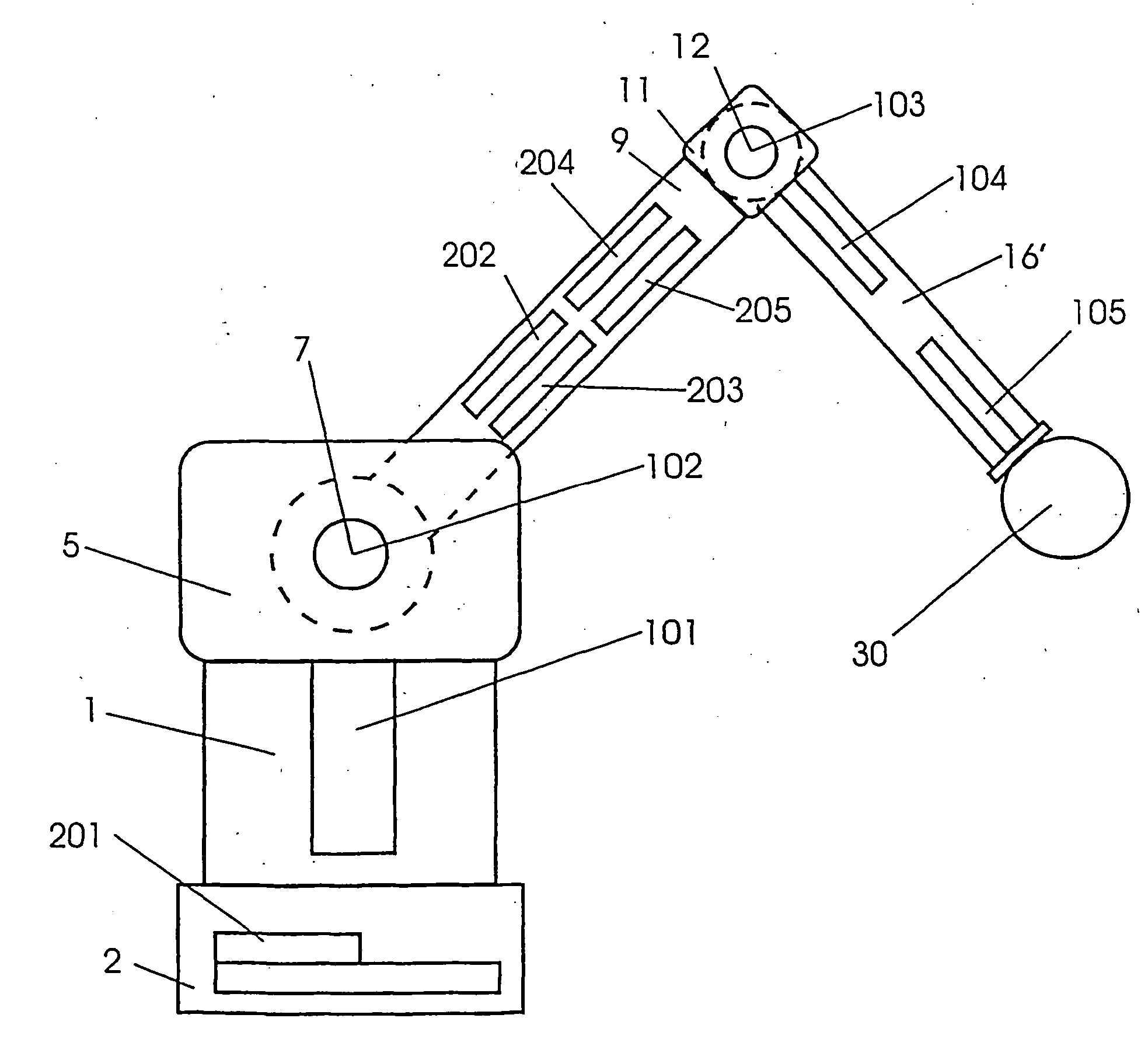
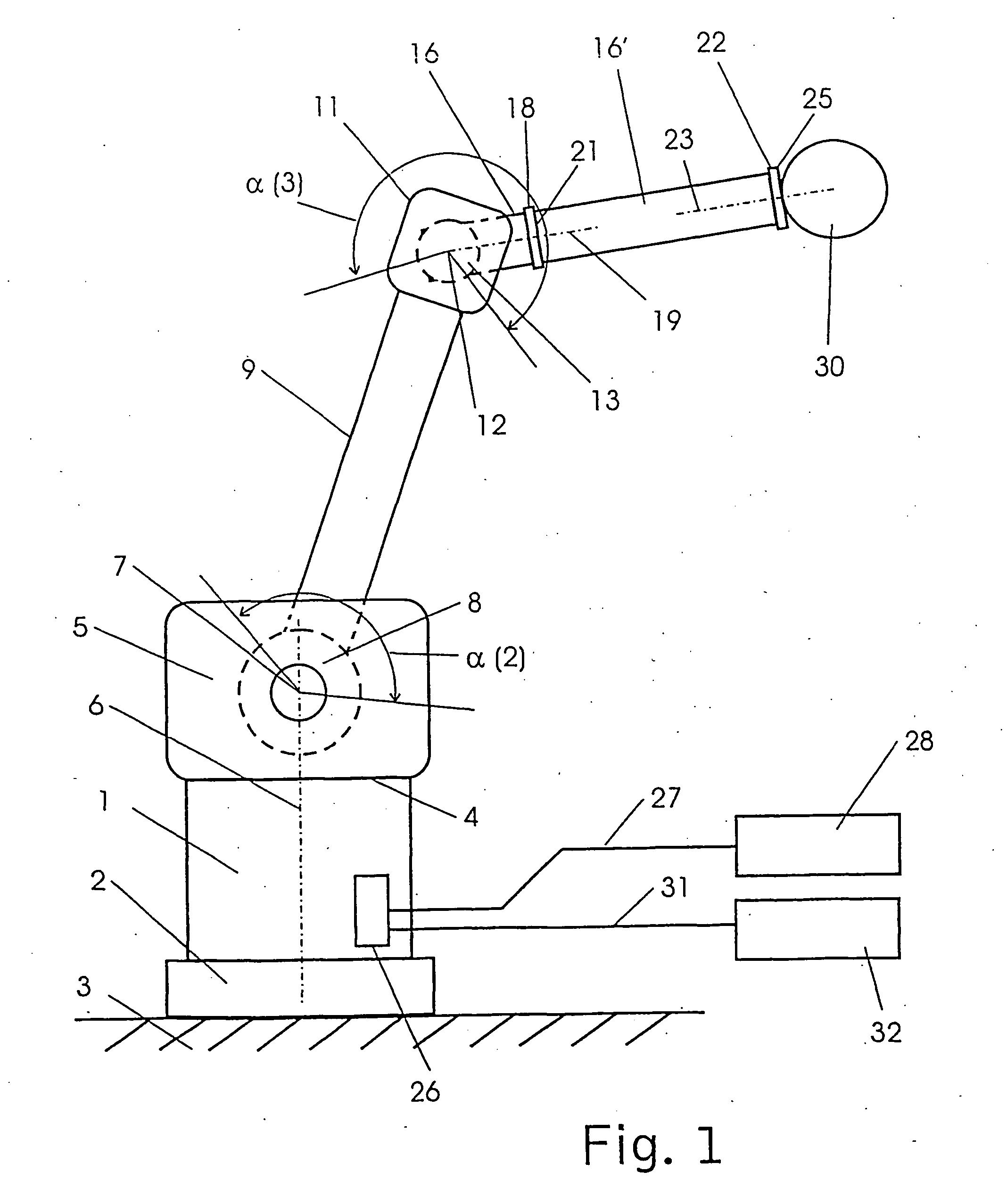
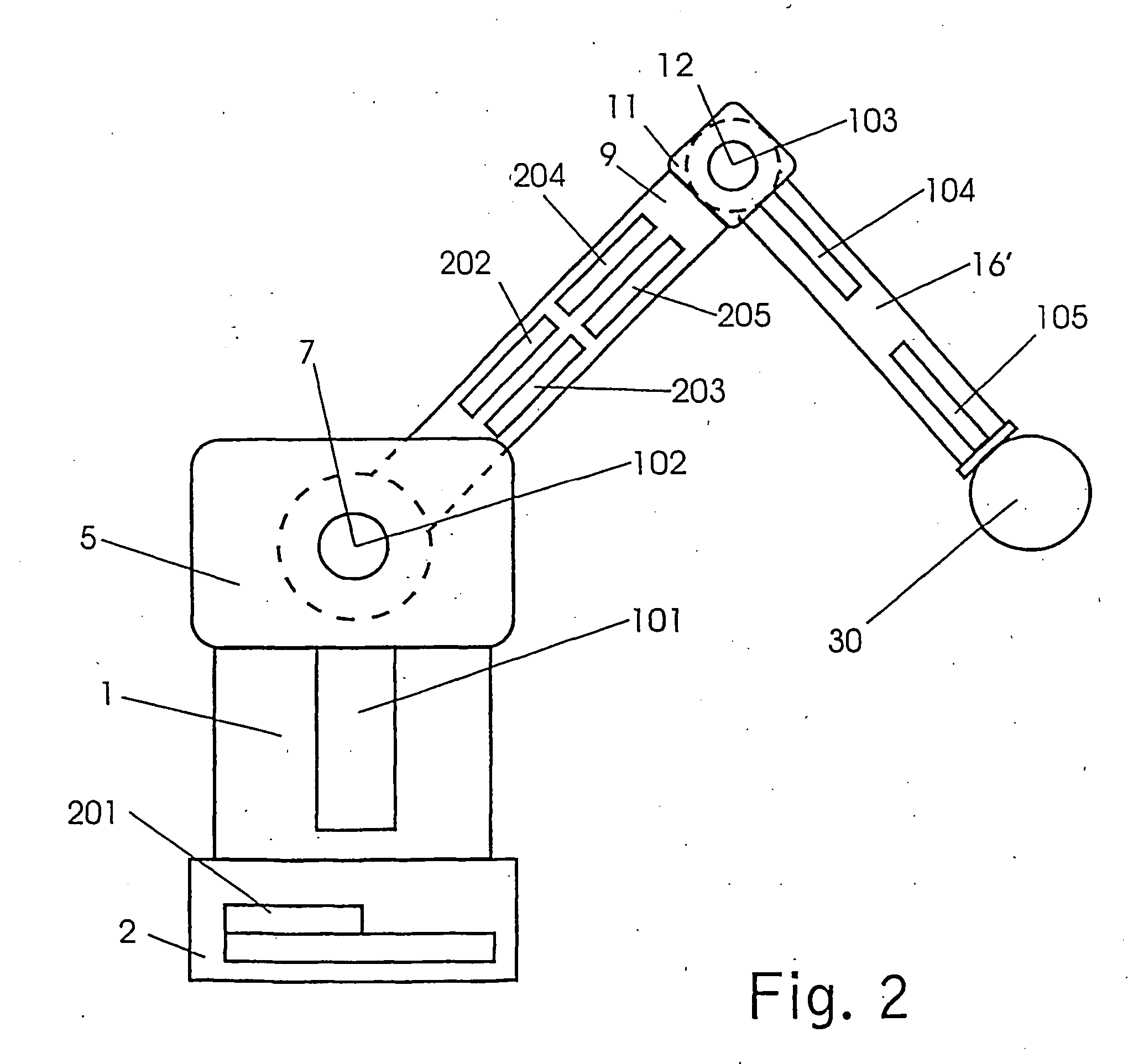
[0027]FIG. 1 shows a schematic diagram of the basic construction of a bending-arm robot. A base element 1 has on its underside a fastening element 2 by means of which it is fastened to a baseplate 3. The upper side of the base element has a horizontal surface 4 on which a joint block 5 is placed flush and is mounted for rotation around an axis 6. The joint block 5 and the base element define a first degree of freedom for a movement around the axis6 with a rotation angle α(1) (not shown) of about 360°.

[0028] The axis runs substantially in the center of the base element 1 and joint block 5. A second axis 7 perpendicular to the axis 6 is arranged in the upper portion of the joint block 5. A joint 8 moves around this second axis 7, is surrounded by a cylindrical support tube 9, also known as “upper arm”, and is fixedly connected to this. The support tube 9 and the joint block 5 define a second degree of freedom for a movement of about 150° around the axis 7, indicated by the rotation a...