Warming gradient control for a cryoablation applicator

Inactive Publication Date: 2006-08-10
CRYOCOR
22 Cites 8 Cited by

AI-Extracted Technical Summary

Problems solved by technology

Subsequently, during warming at a relatively slow warming rate, the small ice cry...

Method used

[0026] In one embodiment of the present invention, a fluid refrigerant is used that transitions from a liquid state to a gaseous state as it expands into the expansion chamber 44 of the cryoelement 40. A suitable refrigerant supply unit 32 for delivering a refrigerant in a liquid state to the distal end of the restriction tube 50 for transition to a gaseous state in the expansion chamber 44 is disclosed in co-pending, co-owned U.S. patent application Ser. No. 10/243,997, entitled “A Refrigeration Source for a Cryoablation Catheter” and filed on Sep. 12, 2002. Co-pending U.S. patent application Ser. No. 10/243,997 was previously incorporated by reference herein. Heat absorbed by the refrigerant during the liquid to gas phase transition (i.e. latent heat) cools the cryoelement 40. After expansion, the gaseous fluid refrigerant passes through the return line 52 and exits at the proximal end 26 of the cryocatheter 24. In one implementation, nitrous oxide is used as the refrigerant with suction applied to the return line 52 allowing the cryoelement 40 to be cooled to a temperature of approximately −85 degrees Celsius. For the system 20, the cryoelement 40 is made of a thermally conductive material (e.g. metal) to allow heat to flow easily between the chamber 44 and the target tissue. FIG. 2 further shows that the catheter 24 can include one or more electrode bands 60, which can be used alone or in conjunction with the conductive cryoelement 40 to map electrical signals of the heart. Those skilled in the pertinent art will appreciate that the cryotip can include other structures (not shown), including sensors, such as one or more pressure sensors or thermocouples, for use in measuring and controlling the temperature of the cryotip.
[0028] For the present methods, effective cell cryoablation is achieved using a regimen of selected cooling and warming rates. Specifically, as shown in FIG. 4, certain tissue cells can be characterized by a relationship of cooling rate versus cell survivability percentage that exhibits a maximum cell survivability percentage at a cooling rate, RMAX. For example, the cells can be cooled at a rate greater than the rate, RMAX, (where the maximum cell survivability percentage occurs) causing intracellular freezing of the tissue cells and the formation of relatively small ice crystals. The size and type of cells that are to be cryoablated are variables that may be considered when determining an effective cooling rate. Additionally, the ice ball that is created during cooling at the target site will af...

Benefits of technology

[0013] During cooling, the temperature of the cells is reduced to below the minimum temperature (e.g. minus 10-15° C.) required to cause the cells to freeze. More typically, the cells are cooled to a temperature (e.g. minus 70° C. to minus 80° C. at the tissue surface) that is substantially below the minimum freezing temperature. In one aspect of the invention, the cells are cooled at a rate greater than the rate, RMAX, (where the maximum cell survivability percentage occurs) causing ...

Abstract

A method for effectively cryoablating tissue cells includes a regimen of selected cooling and warming rates. Specifically, cells are typically ablated by first cooling the cells at a relatively fast cooling rate (e.g. greater than 200° C. per minute) to reduce the cell temperature to below a minimum temperature (e.g. minus 10-15° C.) required to cause the cells to freeze. Next, the cells are thawed using a controlled, relatively slow warming rate (e.g. less than 100° C. per minute). The relatively fast cooling rate can cause intracellular and extra-cellular freezing of the tissue cells and the formation of relatively small ice crystals. Subsequently, during warming at a relatively slow warming rate, the small ice crystals can recrystallize and grow, causing a relatively high rate of cell destruction.

Application Domain

CatheterSurgical instruments for cooling

Technology Topic

High rateWarming rate +8

Image

  • Warming gradient control for a cryoablation applicator
  • Warming gradient control for a cryoablation applicator
  • Warming gradient control for a cryoablation applicator

Examples

  • Experimental program(1)

Example

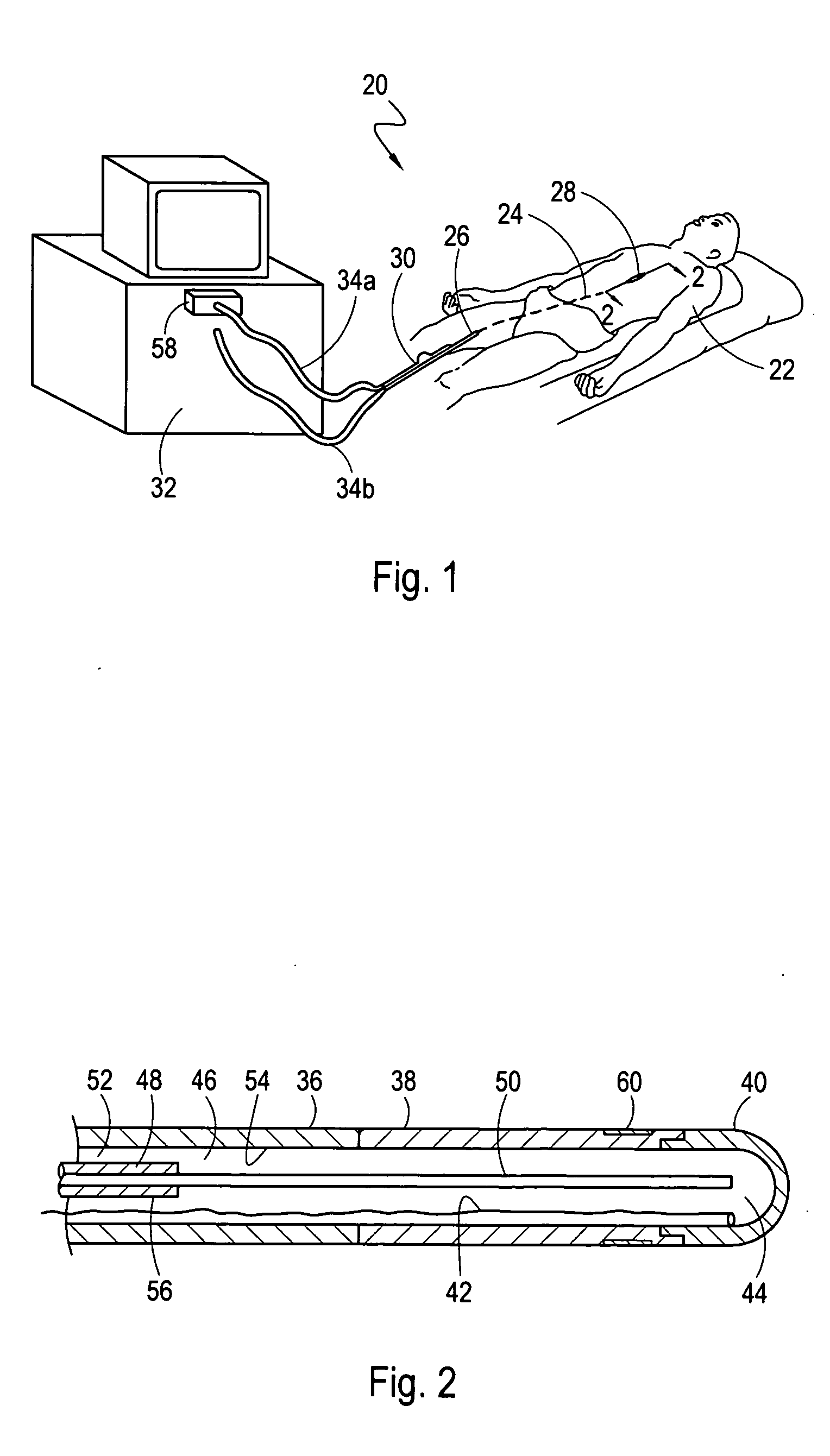
[0021] Referring initially to FIG. 1, a system 20 for ablating internal target tissue of a patient 22 is shown. As shown, the system 20 includes an applicator, which for the embodiment shown is a catheter 24. Although the system 20 is described herein for a catheter 24, those skilled in the pertinent art will appreciate that these methods can be implemented with other applicators such as a cryoprobe (not shown) that is configured to contact and ablate exposed tissue.
[0022]FIG. 1 shows that the catheter 24 extends from a proximal end 26, that remains outside the patient's body during a procedure, to a distal end 28. From FIG. 1 it can also be seen that the distal end 28 of the catheter 24 has been inserted into the patient 22 through a peripheral vein, such as the femoral vein, and advanced through the patient's vasculature until the distal end 28 has been positioned in the upper body of the patient 22. FIG. 1 further shows that the proximal end 26 of the catheter 24 is connected to a catheter handle 30, which in turn is connected to a fluid refrigerant supply unit 32 via a supply line umbilical 34a and a return line umbilical 34b. Although the system 20 is capable of performing a cryoablation procedure in an upper body vessel, such as a pulmonary vein, those skilled in the pertinent art will quickly recognize that the use of the system 20, as herein described, is not limited to use in any one type of vessel, but, instead can be used throughout the human body in vascular conduits and other ductal systems, or by direct application to a target tissue.
[0023] Turning now to FIG. 2, the cryotip (i.e. the distal portion) of the catheter 24 is shown in greater detail. Referring to FIG. 2 and proceeding along the catheter 24 in a proximal to distal direction, it can be seen that the catheter 24 includes a hollow, cylindrical catheter tube 36, an optional articulation segment 38, and a cryoelement 40. The articulation segment 38 can be used to both steer the catheter 24 during an advancement of the distal end 28 of the catheter 24 through body conduits, and to place the cryoelement 40 proximate to the target tissue (see FIG. 3). A suitable articulation segment for use in the system 20 is disclosed in co-pending, co-owned U.S. patent application Ser. No. 10/223,077, filed on Aug. 16, 2002, and titled “Catheter Having Articulation System”. It can also be seen from FIG. 2 that the system 20 includes a pull wire 42 which is attached to the cryoelement 40 and extends to an extracorporeal location (e.g. the handle 30) where the pull wire 42 can be manipulated to selectively reshape the articulation segment 38.
[0024] Continuing now with reference to FIG. 2, it can be seen that the cryoelement 40 is formed with an expansion chamber 44 that is placed in fluid communication with the lumen 46 of the catheter tube 36. Cross-referencing FIGS. 1 and 2, it will be appreciated that the system 20 includes a supply line which includes the supply line umbilical 34a, a supply tube 48 and a restriction tube 50 (e.g. capillary tube) that is positioned at the distal end of the supply tube 48. As shown, the supply tube 48 is positioned in the lumen 46 of the catheter tube 36 and placed in fluid communication with the umbilical 34a. It can be further seen that the supply tube 48 is positioned inside the lumen 46 of the catheter tube 36 to establish a return line 52 between the inner surface 54 of the catheter tube 36 and the outer surface 56 of the supply tube 48. For the system 20, the return line 52 is placed in fluid communication with the return line umbilical 34b.
[0025] Continuing with cross reference to FIGS. 1 and 2, it can be seen that system 20 further includes an adjustable control valve 58 configured to control the pressure in (and flow of refrigerant through) the supply line. With this cooperation of structure, fluid refrigerant from the refrigerant supply unit 32 passes through the valve 58 and into the supply line umbilical 34a. From the umbilical 34a, the fluid refrigerant passes through the handle 30 and into the supply tube 48. The fluid refrigerant then traverses the supply tube 48 and flows into the restriction tube 50. Fluid refrigerant then exits the distal end of the restriction tube 50 and expands into the chamber 44 to cool the cryoelement 40.
[0026] In one embodiment of the present invention, a fluid refrigerant is used that transitions from a liquid state to a gaseous state as it expands into the expansion chamber 44 of the cryoelement 40. A suitable refrigerant supply unit 32 for delivering a refrigerant in a liquid state to the distal end of the restriction tube 50 for transition to a gaseous state in the expansion chamber 44 is disclosed in co-pending, co-owned U.S. patent application Ser. No. 10/243,997, entitled “A Refrigeration Source for a Cryoablation Catheter” and filed on Sep. 12, 2002. Co-pending U.S. patent application Ser. No. 10/243,997 was previously incorporated by reference herein. Heat absorbed by the refrigerant during the liquid to gas phase transition (i.e. latent heat) cools the cryoelement 40. After expansion, the gaseous fluid refrigerant passes through the return line 52 and exits at the proximal end 26 of the cryocatheter 24. In one implementation, nitrous oxide is used as the refrigerant with suction applied to the return line 52 allowing the cryoelement 40 to be cooled to a temperature of approximately −85 degrees Celsius. For the system 20, the cryoelement 40 is made of a thermally conductive material (e.g. metal) to allow heat to flow easily between the chamber 44 and the target tissue. FIG. 2 further shows that the catheter 24 can include one or more electrode bands 60, which can be used alone or in conjunction with the conductive cryoelement 40 to map electrical signals of the heart. Those skilled in the pertinent art will appreciate that the cryotip can include other structures (not shown), including sensors, such as one or more pressure sensors or thermocouples, for use in measuring and controlling the temperature of the cryotip.
Operation
[0027] As best seen by cross-referencing FIG. 1 with FIG. 3, in a typical cryoablation procedure using the system 20, the cryoelement 40 is initially inserted into a body conduit of a patient 22 (e.g. vasculature) and then advanced through the conduit using the catheter tube 36 and handle 30 until the cryoelement 40 is located proximate the target tissue. For example, FIG. 3 illustrates an exemplary application in which the cryoelement 40 has been positioned proximate to tissue surrounding an ostium where a pulmonary vein 62 connects with the left atrium 64. The skilled artisan will appreciate that this tissue can be cryoablated to form a conduction block as a treatment for heart arrhythmias, such as atrial fibrillation.
[0028] For the present methods, effective cell cryoablation is achieved using a regimen of selected cooling and warming rates. Specifically, as shown in FIG. 4, certain tissue cells can be characterized by a relationship of cooling rate versus cell survivability percentage that exhibits a maximum cell survivability percentage at a cooling rate, RMAX. For example, the cells can be cooled at a rate greater than the rate, RMAX, (where the maximum cell survivability percentage occurs) causing intracellular freezing of the tissue cells and the formation of relatively small ice crystals. The size and type of cells that are to be cryoablated are variables that may be considered when determining an effective cooling rate. Additionally, the ice ball that is created during cooling at the target site will affect the cell cooling and cell warming rates. During cooling, the temperature of the cells is reduced to below the minimum temperature (e.g. minus 10-15° C.) required to cause the cells to freeze. More typically, the cells are cooled to a temperature (e.g. minus 70° C. to minus 80° C.) that is substantially below the minimum freezing temperature of the cells.
[0029] After intracellular freezing, the cells are warmed at a relatively slow warming rate, causing the small ice crystals to recrystallize and grow. This process leads to a relatively high rate of cell destruction. The result is an effective way to cryoablate the tissue cells with a relatively low probability of cell survival. In a typical implementation, cells are ablated by first cooling the cells at a relatively fast cooling rate (e.g. greater than 200° C. per minute at the tissue surface) and subsequently allowing the cooled cells to warm at a controlled, relatively slow warming rate (e.g. less than 100° C. per minute). In some applications, a warming rate of less than 50° C. per minute is used, while other applications are performed using a warming rate between 10-50° C. per minute. In certain cases, some tissue cells are destroyed by thrombosis of the included microcirculation (i.e. starvation or suffocation).
[0030] One way to effectuate the cooling/warming regimen described above is to vary the flow of fluid refrigerant in the supply line using the valve 58. Once the cryoelement 40 is proximate the target tissue as shown in FIG. 3, refrigerant is delivered to and expanded in the expansion chamber 44 (see FIG. 2) to cool the cryoelement 40 and target tissue. Refrigerant then flows out of the chamber 44 through the return line 52. By adjusting the valve 58, the flow of coolant through the chamber 44 can be varied to achieve the controlled cooling and warming rates described above. Typically, during the cooling stage, a pre-selected, substantially constant flow of coolant through the chamber 44 is maintained. On the other hand, during the warming stage, the flow of fluid refrigerant through the chamber 44 is slowly reduced by selectively adjusting the valve 58 to achieve a pre-selected, controlled warming rate. Warming at the controlled rate is continued until the tissue cells have warmed to a pre-selected temperature. Moreover, the cooling/warming cycle can be repeated, as desired, to further decrease the probability of cell survival. Once adequate cryoablation has been achieved, the cryoelement 40 is removed from the patient 22 to complete the procedure.
[0031] While the particular Warming Gradient Control For A Cryoablation Applicator and corresponding methods of use as herein shown and disclosed in detail are fully capable of obtaining the objects and providing the advantages herein before stated, it is to be understood that they are merely illustrative of the presently preferred embodiments of the invention and that no limitations are intended to the details of construction or design herein shown other than as described in the appended claims.

PUM

no PUM

Description & Claims & Application Information

We can also present the details of the Description, Claims and Application information to help users get a comprehensive understanding of the technical details of the patent, such as background art, summary of invention, brief description of drawings, description of embodiments, and other original content. On the other hand, users can also determine the specific scope of protection of the technology through the list of claims; as well as understand the changes in the life cycle of the technology with the presentation of the patent timeline. Login to view more.

Similar technology patents

Classification and recommendation of technical efficacy words

  • High rate
  • Low probability

Method for management of timeouts

InactiveUS20090320030A1Low probabilityMultiprogramming arrangementsMemory systemsExpiration TimeCurrent time
Owner:IBM CORP

Cyclic transmission of notification coordinates in a communication system

InactiveUS20050288040A1Low battery power consumptionLow probabilityPower managementFrequency-division multiplex detailsReal-time computingGroup identifier
Owner:PANASONIC CORP
Why Eureka
Try Eureka