Quasi-redundant smart sensing topology

Inactive Publication Date: 2006-08-10
GM GLOBAL TECH OPERATIONS LLC
View PDF32 Cites 14 Cited by
  • Summary
  • Abstract
  • Description
  • Claims
  • Application Information

AI Technical Summary

Benefits of technology

[0006] The present invention overcomes the shortfalls of redundant sensing and spatial diversity. In accordance with the present invention, a sensor assembly for measuring a predetermined parameter includes a plurality of sensing elements. The sensing elements are integrated within a unitary sensor package. Each of the sensor elements is operative in accordance with a unique sensing principle to provide a respective measurement signal corresponding to the predetermined parameter. A signal processor is integrated within the u

Problems solved by technology

Of course, the more sensors used in a redundant array, the more processor resources are required and consumed.
In such redundant sensor arrangements, data fusion and validation are also performed by the microprocessor or PLC, thereby consuming even more of the limited processor resources and being subject to processor cycle delays and throughput constraints.
Validating individual sensors among only a pair of sensors is difficult where no information about the sensors is available apart from the data at the inputs of the microprocessor or PLC.
Of course, as alluded to, more sensors require more of the already limited input points and processor resources, consume additional space and provide additional system cost.
While this may eliminate the need for most custom post-processing at the microprocessor or PLC, a redundant sensor arrangement o

Method used


Image

  • Quasi-redundant smart sensing topology
  • Quasi-redundant smart sensing topology
  • Quasi-redundant smart sensing topology

Examples


Example

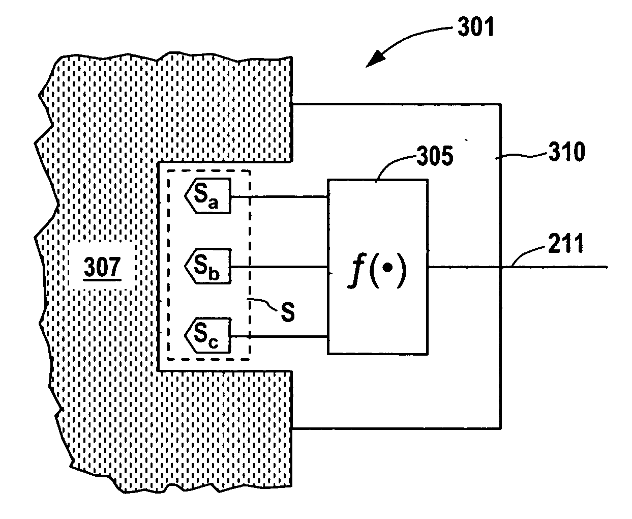
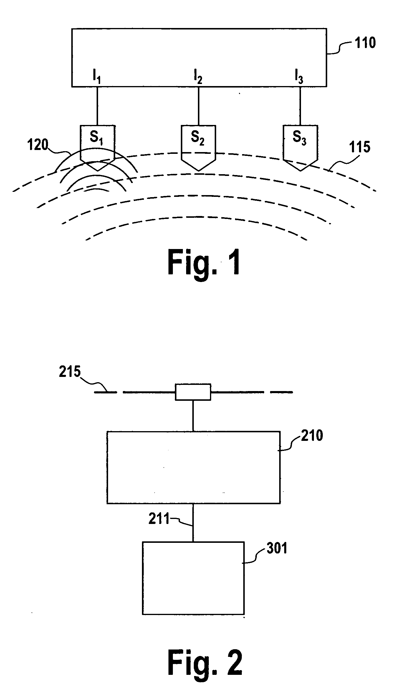
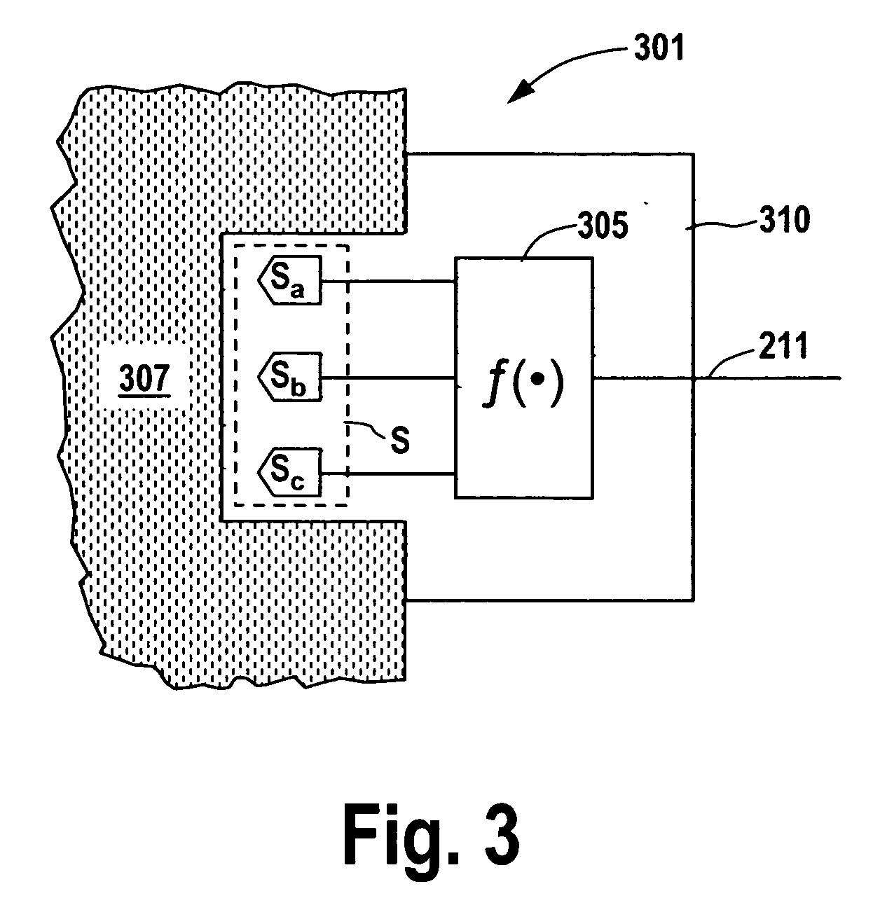
[0015] The present invention will now be described with reference to FIGS. 2 and 3 which illustrate an embodiment of a quasi-redundant, multi-element smart-sensor 301 in application with a microprocessor or PLC based control 210. Sensor 301 is shown in operative communication with control 210 via line 211 in the figure. Line 211 comprises any of a variety of appropriate communication means including hardwired or wireless communications. In hardwired communications, data transmission comprises serial or parallel data in accordance with the particular application. For example, high speed applications may benefit from parallel bus communication whereas in applications wherein high speed communication is not so critical, serial data transmission may be sufficient. Control 210 may be an independent control or part of a more complex network of additional controllers (not separately illustrated) communicating via any of a variety of bus / networks 215, including closed and open networks. Tho...


PUM


Abstract

A sensor apparatus includes a plurality of sensing elements within an integrated sensing package. Each sensing element is directed at sensing the same parameter. Each sensing elements operates under a principle that is unique from the others thereby providing individual parameter measurements that are substantially immune from common mode effects due to generic influences upon the sensing elements and may exhibit different failure modes. Sensing element signals are acquired, validated and fused within the integrated sensing package, preferably with micro-controller based circuitry. A single output from the sensor apparatus is communicated directly to a programmable logic controller, microprocessor or over a network or other bus.

Description

TECHNICAL FIELD [0001] The present invention is related to sensing systems. More particularly, the present invention relates to so-called smart sensors. BACKGROUND OF THE INVENTION [0002] Many sensing systems employ redundant sensing to improve the accuracy and robustness of their measurements. Such systems are characterized by a plurality of substantially identical sensors configured to measure a predetermined parameter. Essentially, redundancy is based upon simple repetition of the functionality of the same type of sensor either in the same or in different locations. [0003] As illustrated in FIG. 1, each sensor (Sn) in such a redundant arrangement requires one of a limited number of inputs (In) at a microprocessor or programmable logic controller (PLC) 110. In other words, there is a one-to-one mapping of sensors to input points. Each sensor therefore requires significant processor or PLC system resources for such signal processing tasks as signal conditioning and filtering, analo...

Claims


Application Information

Patent Timeline
IPC IPC(8): G06F15/00
CPCG01K7/42G01K15/00G01K2205/00
Inventor BARAJAS, LEANDRO G.
Owner GM GLOBAL TECH OPERATIONS LLC
Why Eureka
Try Eureka