Disk array device

a technology of array devices and drives, applied in the direction of instruments, computing, electric digital data processing, etc., can solve the problems of system downtime, response delay, and hdd may not respond to the access request for the normal data read/write from the dkc for the required time, so as to prolong the life of the drive and improve reliability. , the effect of reducing the reliability

Inactive Publication Date: 2006-08-10
HITACHI LTD
View PDF3 Cites 13 Cited by
  • Summary
  • Abstract
  • Description
  • Claims
  • Application Information

AI Technical Summary

Benefits of technology

[0008] (1) Even if the disk array device employs the storage unit having somewhat lower reliability such as the SATA drive, means for extending the life span of the drive as an individual body thereby the reliability is improved is considered.

Problems solved by technology

(2) However, if the means for improving the reliability of the individual drive is used, the HDD may not respond to the access request for the normal data read / write from the DKC for the required time such as within several seconds (hereinafter referred to as “response impossible state”.
In the environment that the above-described response impossible state in the HDD may be occurred, if the target data does not exist on CM when the request for the data I / O is issued from the host, an access to the pertinent HDD in which the target data is stored is occurred, however, when the pertinent HDD can not respond, an response delay is occurred.
In the system which issues such I / O strictly required the response, if the disk array device can not normally respond to the host system within the time limit (hereinafter referred to as required response time), an error and system down may be occurred.
That is to say, provided that the HDD to be accessed can not respond when the critical I / O request from the host is received at DKC, an error and so forth is occurred if the HDD can not respond within the required response time due to the answer delay.
However, adversely, if the required response time from the host in the I / O is shorter than the duration for the response impossible state in the HDD to be accessed, an answer delay and so forth is occurred so that it results in error.

Method used


Image

  • Disk array device
  • Disk array device
  • Disk array device

Examples


embodiment 1

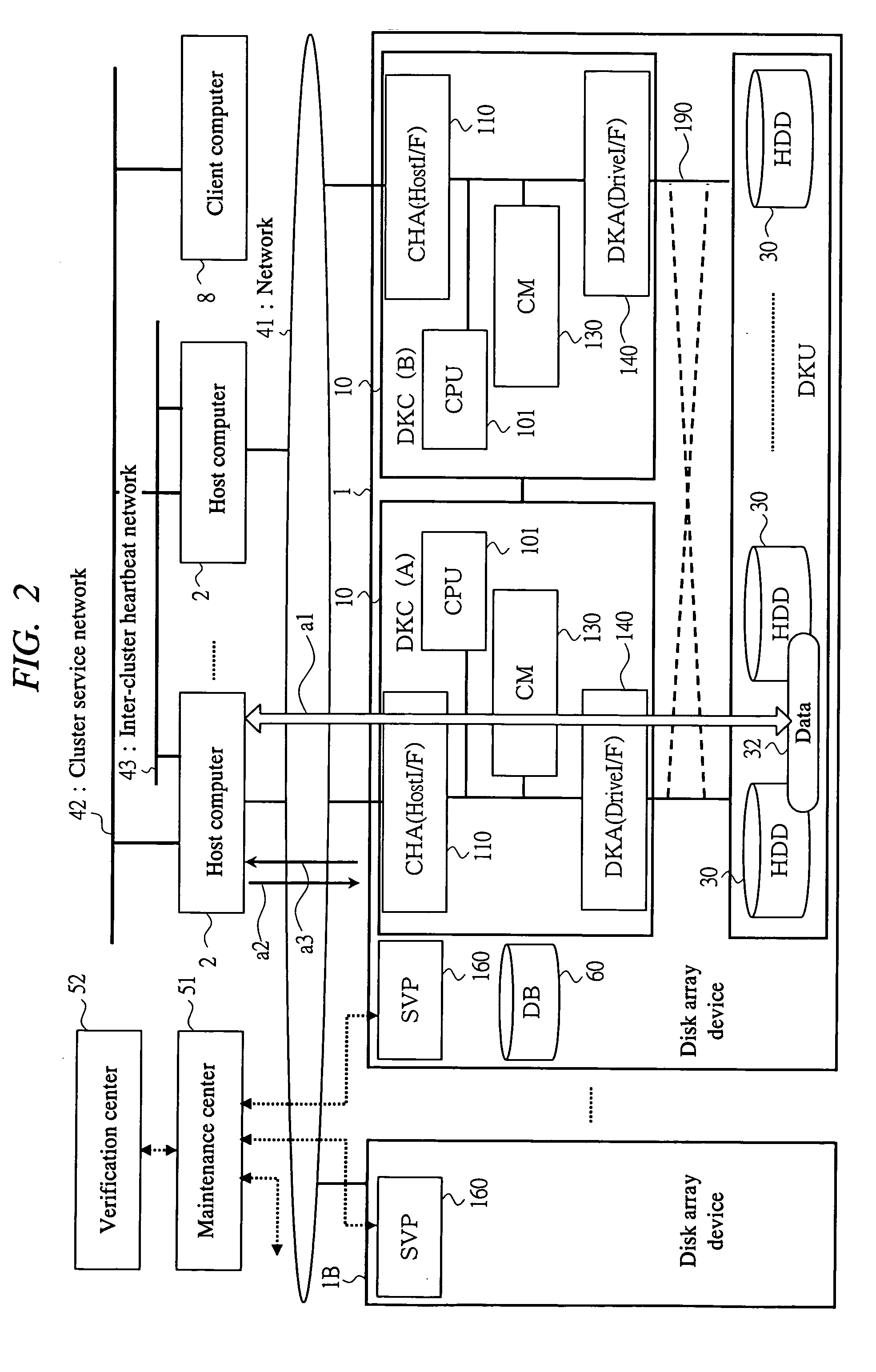
[0040] The disk array device 1 according to the first embodiment of the present invention is described with reference to FIG. 1-FIG. 10. In the first embodiment, the DKC 10 compares the actual I / O pattern from the host 2 with the defined I / O pattern to extract the specified I / O pattern, previously performs the cache control according to the cache control information corresponding to the specified I / O pattern and then, responds to the critical I / O from the host system using the cache controlled data by the first means composed of the hardware and the software.

[0041]1)>

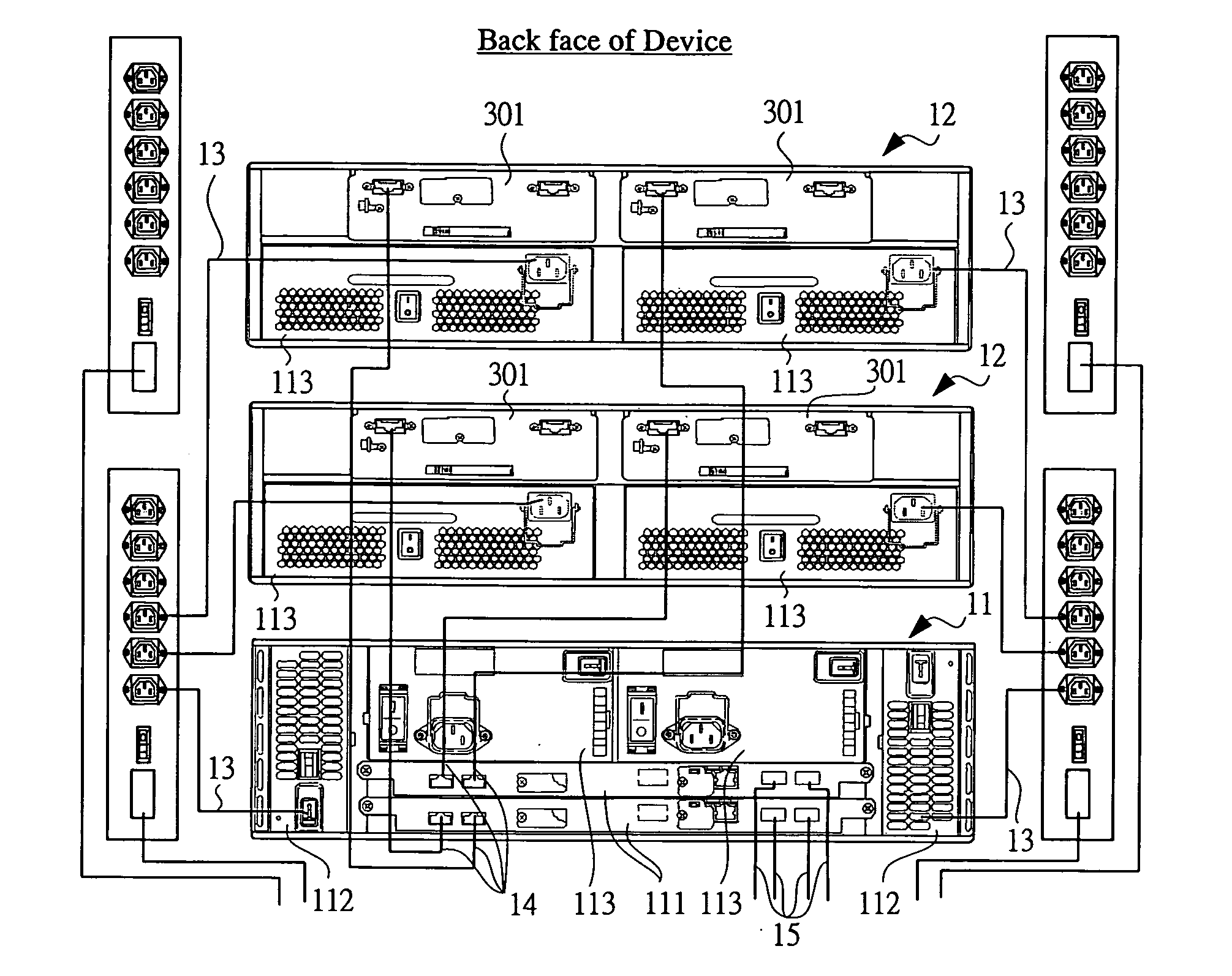
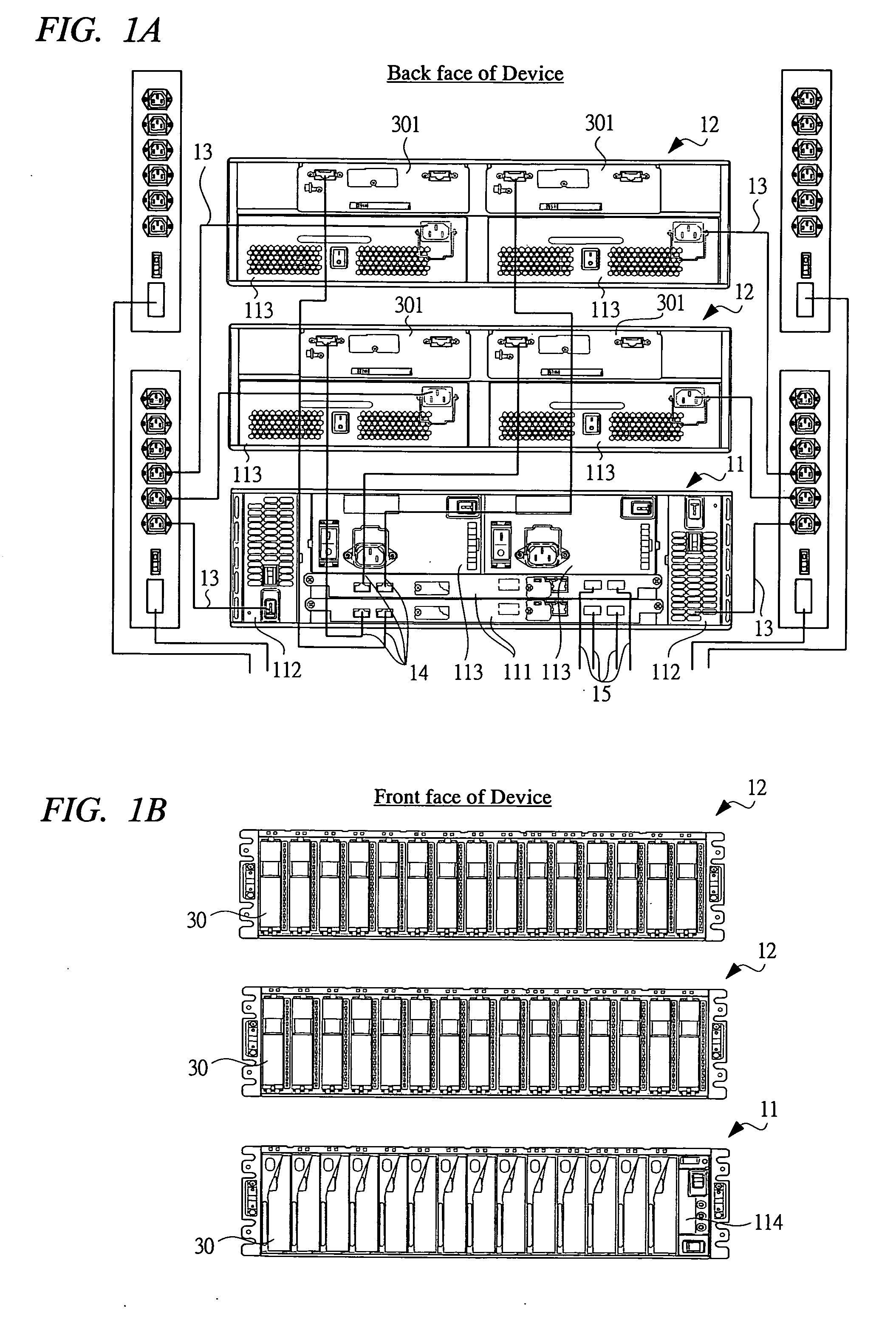
[0042]FIGS. 1A and 1B are a block diagram of the appearance of the overall hardware of the disk array device 1. The configuration is common to each embodiment of the present invention. The disk array device 1 can be constructed of a base housing and a plurality of additional housings, for example. FIG. 1A represents the connection structure of the back face of the device and each housing therebetween. Where, a base hou...

embodiment 2

[0191] Next, the disk array device 1 according to the second embodiment of the present invention is described with reference to FIG. 1-FIG. 10. In the second embodiment, second means composed of the hardware and the software captures information such as the I / O trace based on the I / O from the host system, and the information is used to respond to the critical I / O from the un-corresponding and unknown host system to the defined DB 60A.

[0192] If the host system configuration is matched with the information registered in the defined DB 60A, the critical I / O can be responded under the above-described control in the first embodiment. In the case of the system configuration according to the specific OS, middleware and application in the host 2, the cache control information 73A corresponding thereto is previously created and stored in the disk array device 1 so that it is possible to respond, for example.

[0193] However as for an unknown host system, such as the combination of each versi...

embodiment 3

[0202] Next, the disk array device 1 according to the third embodiment of the present invention is described with reference to FIG. 1-FIG. 10. In order also to respond to the change of the configuration due to the version up of such as the OS and the correction at the patch level in the host system, the disk array device 1 is provided with means as third means for applying the cache control information 73 the same as the similar host system to perform the cache control thereby to respond the critical I / O if the actual I / O pattern from the host 2 is similar to the defined I / O pattern in the third embodiment.

[0203]

[0204] In the third embodiment, the similarity determination process is performed in the step s10 of FIG. 7. The DKC 10 compares the actual I / O pattern from the host 2 or the captured I / O trace information with the defined I / O pattern information 72 A in the defined DB 60A and extracts the specified I / O pattern to determine. As for the determination, not only the case that ...


PUM


Abstract

In the disk array device, the critical I/O from the host can be responded regardless of the state of the storage unit to be accessed and without occurring an answer delay and system down so that both of the I/O performance and the system reliability can be improved. In the disk array device, a DKC to control data storage to a HDD includes CM to perform the data I/O processing to the HDD responsive to the I/O request from the host. A response impossible state due to the life extension process may be occurred in the HDD. The DKC determines the specified I/O pattern in the received I/O and previously performs the cache control to the critical I/O target data associated with the specified I/O pattern using a CM according to the information in the DB. The critical I/O request is responded using the cache resident data on the CM.

Description

CROSS-REFERENCE TO RELATED APPLICATION [0001] The present application claims priority from Japanese Patent Application JP 2005-034692 filed on Feb. 10, 2005, the content of which is hereby incorporated by reference into this application. TECHNICAL FIELD OF THE INVENTION [0002] The present invention relates to a disk array device (storage device) having a storage unit such as a hard disk drive (HDD) and a storage control unit (hereinafter referred to as DKC) to control data storage to the storage unit and being capable of performing RAID control. Especially, the present invention relates to a technology for improving data input / output (I / O) utilizing a cache memory (CM), and a technology for improving the system reliability. BACKGROUND OF THE INVENTION [0003] (1) The disk array device as an external storage unit has response capability to store data in a storage volume on the disk array responsive to an I / O request and a command from the other devices such as a host computer (hereina...

Claims


Application Information

Patent Timeline
Patent Type & Authority Applications(United States)
IPC IPC(8): G06F3/00
CPCG06F3/0605G06F3/0611G06F3/0616G06F3/0653G06F3/0659G06F3/067G06F12/0866
Inventor MURAMATSU, RYOSUKEOKADA, KOICHITAMURA, AKIYORI
Owner HITACHI LTD
Why Eureka
Try Eureka