Split L2 latch with glitch free programmable delay

a programmable delay and latch technology, applied in the field of l1l2 latch chains, can solve problems such as glitches, inability to complete all proposals at once, and corrupt data flow from l1 to l2

Inactive Publication Date: 2006-08-10
IBM CORP
View PDF8 Cites 1 Cited by
  • Summary
  • Abstract
  • Description
  • Claims
  • Application Information

AI Technical Summary

Benefits of technology

[0006] One object of the invention is the provision of a C2 clock delay circuit that allows the outpu

Problems solved by technology

However, these proposals have not been all together successful.
One problem with prior art proposals for delaying the L2 clock signal it that it introduces glitches.
This can cause glitching (unintended false switching to 1 or 0) on the delay_out signal, which can corrupt

Method used


Image

  • Split L2 latch with glitch free programmable delay
  • Split L2 latch with glitch free programmable delay
  • Split L2 latch with glitch free programmable delay

Examples


Embodiment Construction

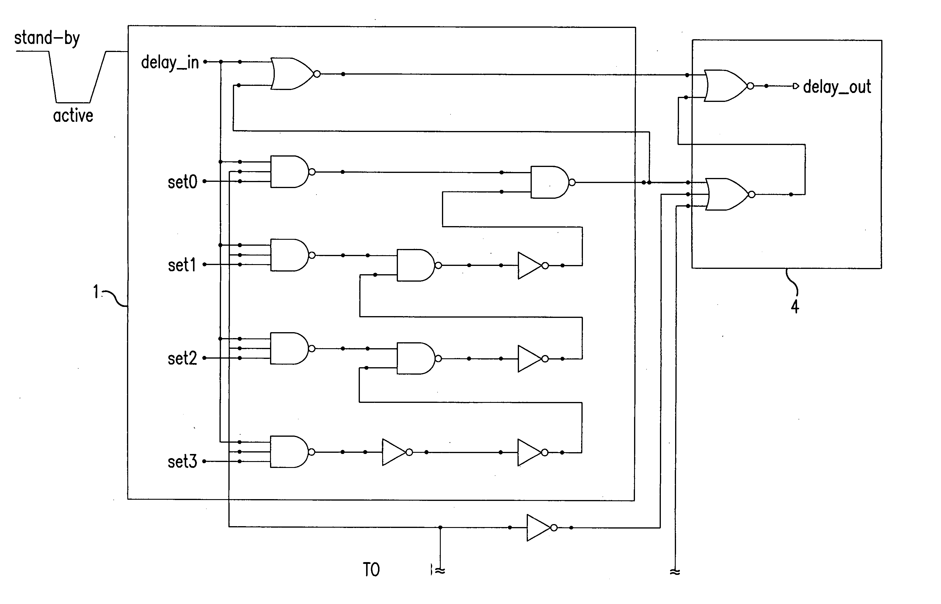
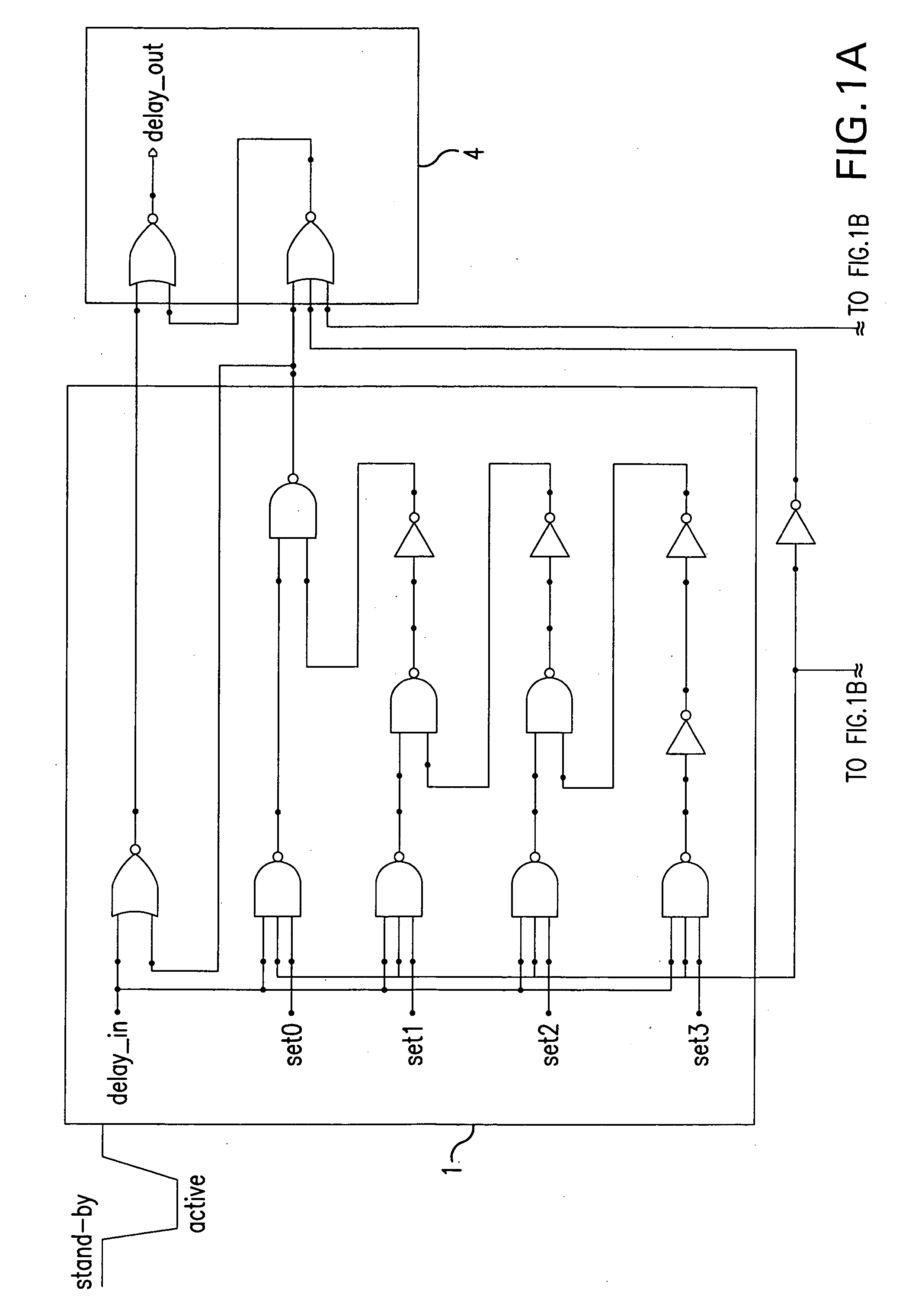
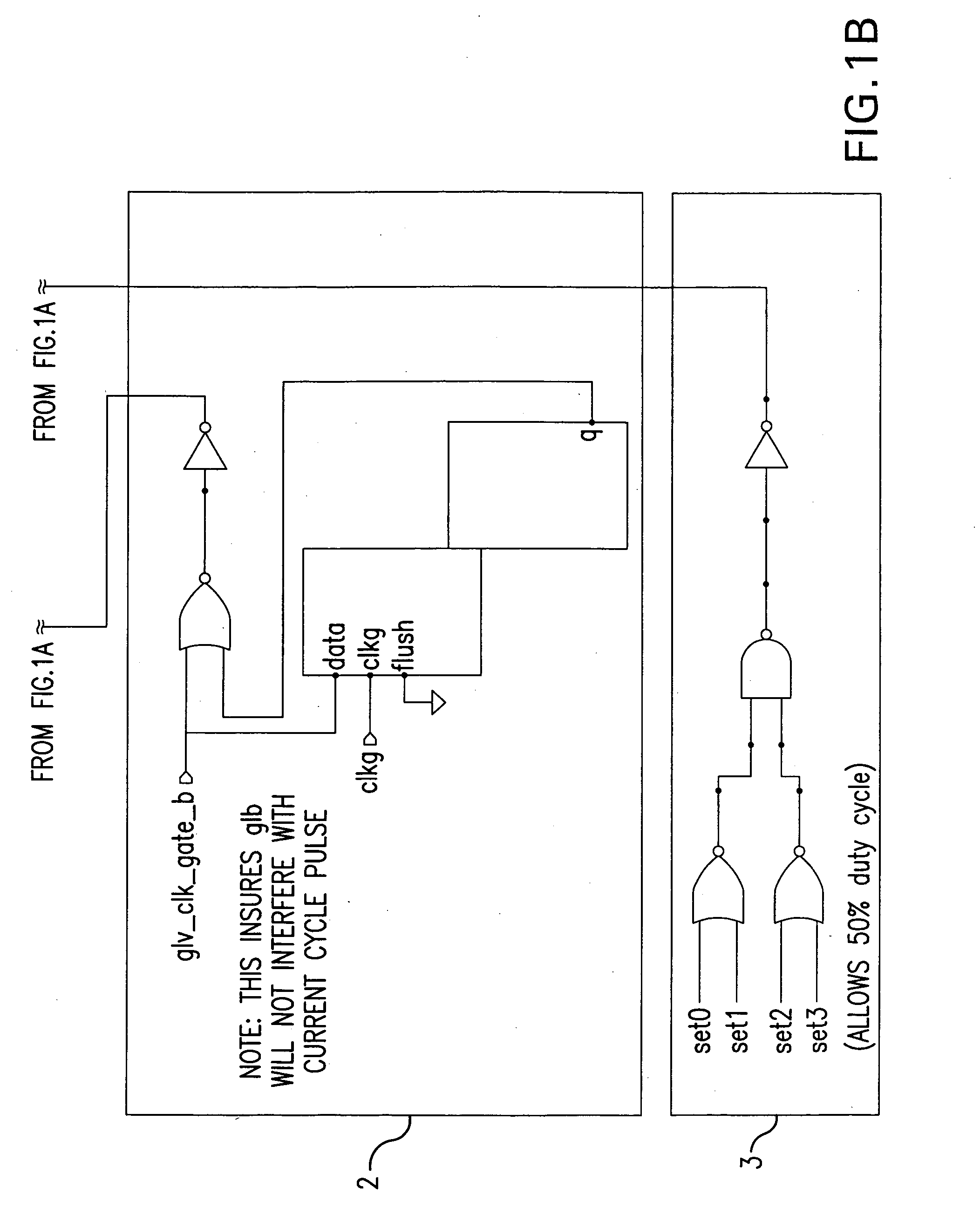
[0013] Referring now to FIGS. 1A and 1B, specific embodiment of the C2 delay clock generator of this invention shown in FIGS. 1A and 1B has four functional components; a programmable C2 clock delay circuit shown in block 1, a scan mode delay inhibit circuit shown block 2; a constant C2 clock cycle circuit shown in block 3, and C2 clock output circuit shown in block 4. In the programmable C2 clock delay circuit of block 1, the C2 clock is coupled via the delay_input terminal to an exclusive NOR gate 12 and to one input terminal of each of four exclusive three input AND gates 14. In this specific embodiment of the invention, the C2 clock is active low, and may be the complement of the C1 clock Programmable bits held in mode latches (not show) are coupled to the set0, set1, set2, and set3 inputs of the gates 14. The input in put of each gate 14 is connected to the C2 clock input terminal delay_in. The outputs of 14 are connected in a chain from bottom to top in the drawing. The amount ...


PUM


Abstract

A programmable delay circuit that delays the C2 clock signal by a variable amount that allows the output from the L1 latch to be captured even when there is a large delta between the L1 latch and its L2 latch. This allows the C2 signal to be adjusted within the system dependent upon the amount of cycle steal is needed. The C2 clock delay is inhibited during scan operation to prevent glitches and the trailing edge of the delayed C2 is controlled to maintain a constant C2 duty cycle.

Description

CROSS REFERENCE TO RELATED APPLICATIONS [0001] This application contains subject matter that is related to the subject matter of the following co-pending applications, each of which is assigned to the same assignee as this application, International Business Machines Corporation of Armonk, N.Y., and is filed concurrently herewith. Each of the below listed applications is hereby incorporated herein by reference. High Speed Domino Bit Line Interface Early Read and Noise Suppression, Attorney Docket POU9 2004 0217; Global Bit Select Circuit With Dual Read and Write Bit Line Pairs, Attorney Docket POU9 2004 0214; Local Bit Select Circuit With Slow Read Recovery Scheme, Attorney Docket POU9 2004 0224; Global Bit Line Restore Timing Scheme and Circuit, Attorney Docket POU9 2004 1234; Local Bit Select With Suppression, Attorney Docket POU9 2004 0246. BACKGROUND OF THE INVENTION [0002] 1. Field of the Invention [0003] This invention relates to L1-L2 latch chains, and more particularly to an...

Claims


Application Information

Patent Timeline
IPC IPC(8): G01R31/28
CPCG01R31/318552
Inventor CHAN, YUEN H.FREESE, RYAN T.PELELLA, ANTONIO R.
Owner IBM CORP
Why Eureka
Try Eureka