
Joining device and joining process

Inactive Publication Date: 2006-08-17
FORD GERMANY +1
View PDF6 Cites 16 Cited by
  • Summary
  • Abstract
  • Description
  • Claims
  • Application Information

AI Technical Summary

Benefits of technology

[0004] The object of the present invention is to provide an improved joining technique.
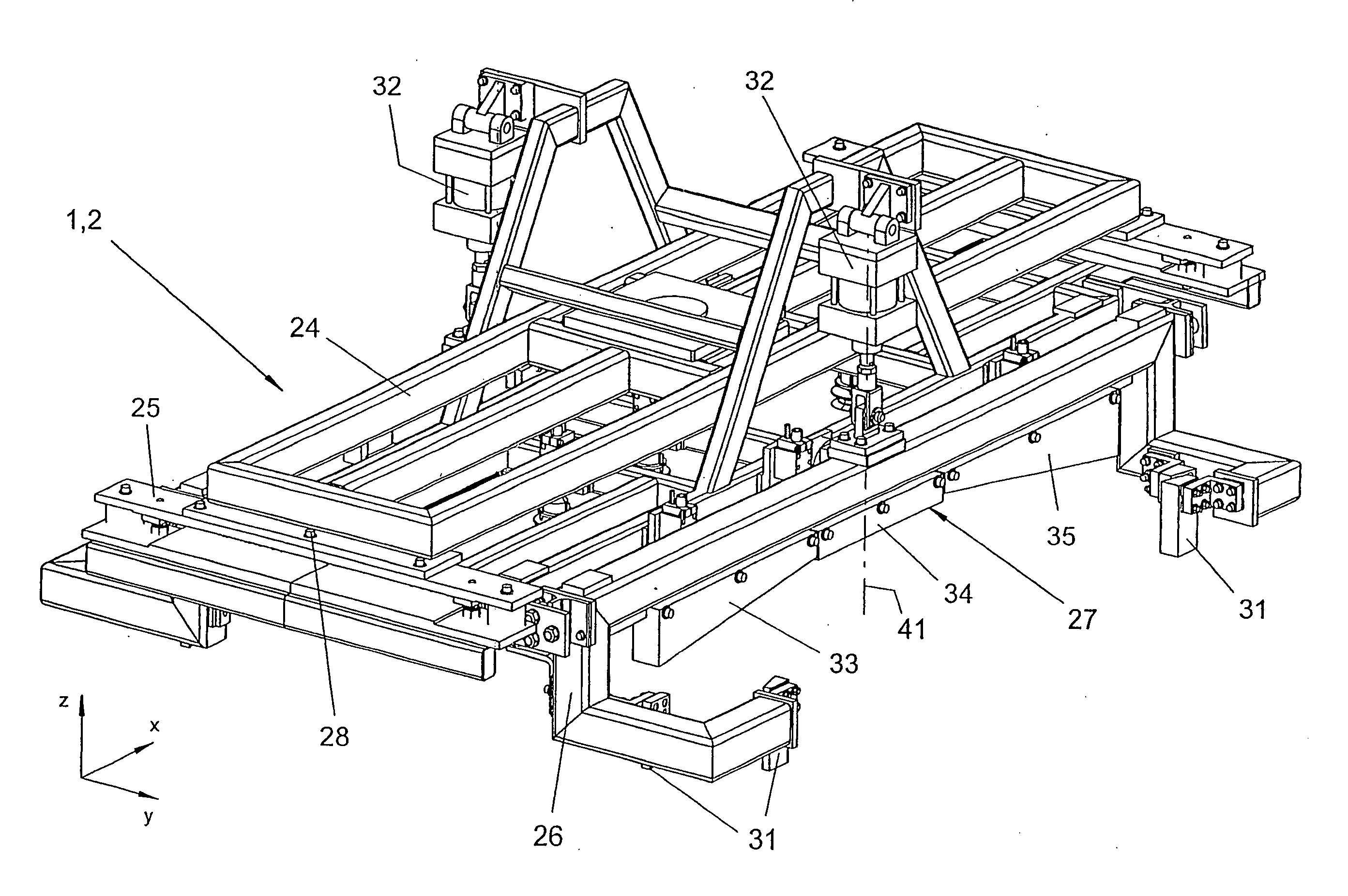
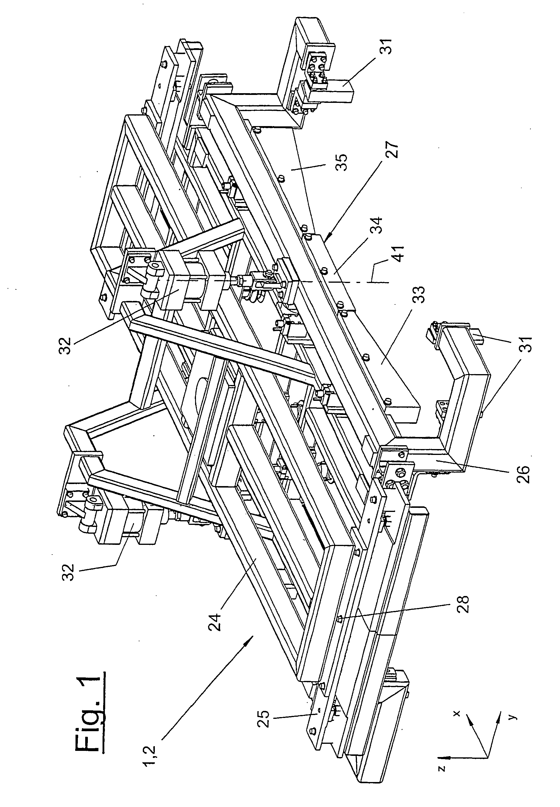
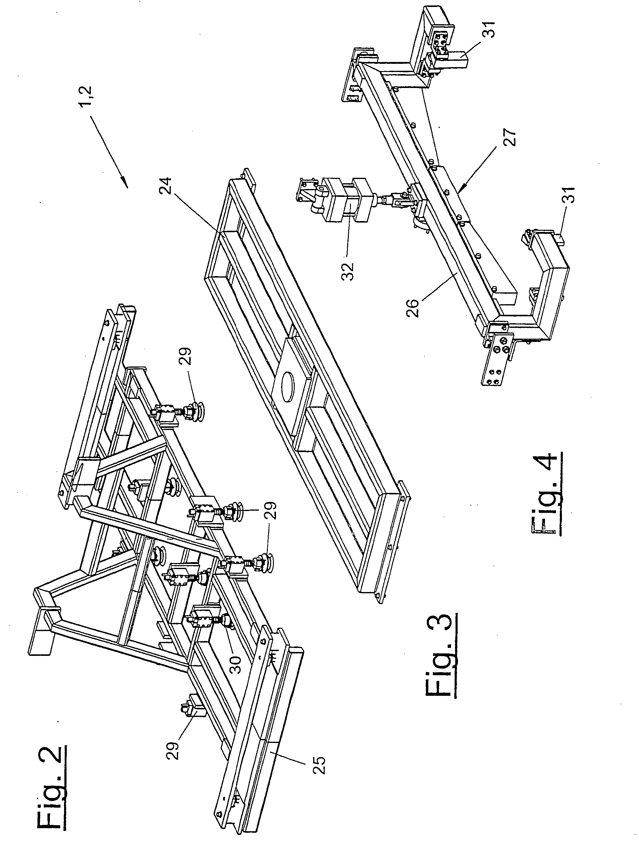
[0006] The division of the pressing strip into a plurality of strip segments has the advantage of better and more accurate adaptation of the shape to the existing joining contour of the components. Moreover, local tolerances can be absorbed better and more reliably. The mutually independent, flexible mounting of the strip segments is advantageous for this. The pressing force of the individual segments of the strip is guaranteed by corresponding spring elements. Contrary to the prior-art pressing tube, the pressing force and the active shaping can now be applied in a targeted manner in the needed areas of the joining contour that are subject to tolerance due to the dimensional stability of the pressing strip.
[0009] The joining means according to the present invention makes it, furthermore, possible to grip the parts to be joined in an accurately fitting manner and to accurately position and center them for the subsequent fixing or permanent connection. Corresponding guides and a centering device oriented toward the component, especially the joining contour of the component, are advantageous for this.

Problems solved by technology

The pressing tube extending over the entire length of the roof panel ensures a pressure that is constant everywhere, which is useful for the prevention of deformation, but, on the other hand, does not guarantee reliable contact of the roof panel with the supports of the side panels.
After the roof panel has been connected to the side panels by laser soldering, this insufficient pressing may lead to problems due to the formation of gaps, especially if the side parts of the body have position tolerances and are directed, e.g., crooked with their supports.
The soldered connection may be insufficient in this case.

Method used


Image

  • Joining device and joining process
  • Joining device and joining process
  • Joining device and joining process

Examples


Embodiment Construction

[0047] Referring to the drawings in particular, FIGS. 5 through 7 and 11 show different embodiments of a machining station (44) with a joining device (1). The machining station (44) is part of a manufacturing plant for bodies (3) or body shells of vehicles and may be present as several copies and integrated in a transfer line in this case. The body (3) comprises, e.g., a floor group (not shown) and one or more components (4), here two side panel parts, which are optionally connected to one another and stiffened by an inserted roof bow (not shown) in the area of the roof. The body is held by a component mount (46), e.g., a pallet and transported along the transfer line.

[0048] A part to be joined (I 1), which comprises, e.g., a thin-walled and optionally preformed roof panel, is joined with the joining device (1) on the body (4) [sic—Tr.Ed.] or the side panel parts (4). It is now fed to the joining site, positioned in a position that is correct for the joining there, held firmly in t...


PUM

PropertyMeasurementUnit
Flexibilityaaaaaaaaaa
Areaaaaaaaaaaa
Heightaaaaaaaaaa

Abstract

A joining method and to a joining device (1) for joining roof skins (11) to parts (4) of vehicle bodies (3) is provided. The joining device (1) includes one or more joining grippers (2), which are comprised of at least one frame (24), of a number of gripping elements (29, 30), of at least one pressing strip (27), which acts upon the roof skin (11), and of an associated adjusting device (32). The pressing strip (27) is adapted to the joining contour (6) of the part (4) and has one or more dimensionally stable strip segments (33, 34, 35, 36, 37) that, independent of one another, are mounted on a strip support (26) with a limited flexibility in the direction of adjustment (41). The roof skin (11) with the joining part edge (13) thereof, is pressed against and fixed to the contact area (7) of the part (4) by means of the strip segments (33, 34, 35, 36, 37) and, optionally, is permanently deformed.

Description

CROSS REFERENCE TO RELATED APPLICATIONS [0001] This application is a United States National Phase application of International Application PCT / EP2004 / 002151 and claims the benefit of priority under 35 U.S.C. § 119 of German Application DE 103 10 194.2 filed Mar. 6, 2003, the entire contents of which are incorporated herein by reference.FIELD OF THE INVENTION [0002] The present invention pertains to a joining means and a joining process for parts to be joined, especially roof panels. BACKGROUND OF THE INVENTION [0003] Such a joining means with a joining process is known from DE-A-100 61 309. The technique is used to join roof panels on side panels of vehicle bodies by means of a joining gripper. The joining gripper comprises a robot-guided frame with a plurality of suction grippers and peripherally arranged pressing tubes acting on the part to be joined. The longitudinally extending edges of the roof panel shall be pressed with these pressing tubes against the supports at the side pa...

Claims


Application Information

Patent Timeline
IPC IPC(8): B23Q7/00B23K37/04B23K37/047B62D65/06
CPCB23K37/0443B23K37/047Y10T29/5196B62D25/06B23P2700/50
Inventor STURM, THOMAS
Owner FORD GERMANY
Learn More