Acoustic wall using compressed fiber panels

a technology of compressed fiber panels and walls, applied in walls, construction, building components, etc., can solve the problems of less than optimal construction, and acoustic short circuits around resilient channels negating the full effect, so as to improve acoustics and eliminate easy burn through areas

Inactive Publication Date: 2006-08-17
STRAWMEN
View PDF36 Cites 12 Cited by
  • Summary
  • Abstract
  • Description
  • Claims
  • Application Information

AI Technical Summary

Benefits of technology

[0015] The present invention includes a structure and a method for building the structure for a sound insulating wall. The sound insulating wall is useful for improving acoustics in commercial buildings, theaters. It has a multi-layer construction formed from at least three compressed strawboard panels in adjacent and generally parallel planar alignment and defining spaces in between which can be hollow or filled with insulating medium. Each panel is held in place by opposed edge bracket assemblies positioned to clasp the ends of each panel. The bracket assemblies include a resilient material acting to isolate or decouple each panel. The strawboard panels are positioned so that horizontal panel to panel joints in each layer are offset to eliminate easy burn through areas. Edge brackets are generally mounted to vertical I-beams and can be adapted for use with a variety of beam types.

Problems solved by technology

The higher the STC rating, the greater the sound transmission loss.
Historically, however, less than optimum construction and installation practices effectively lead to acoustic short circuits around resilient channels negating their full effect.
In some cases, the cells of the honeycomb core effectively trap dead air which is a relatively poor acoustic conductor.
It is known that sound insulation is best obtained from multi-shell components wherein both the mass and the resiliency of the components are factors, thus a best combination of weight and bulk is typically sought New materials, namely novel viscoelastic polymers included as part of layered panels or are finding use in high STC wall construction, but these materials tend to be expensive and remain largely unproven.

Method used


Image

  • Acoustic wall using compressed fiber panels
  • Acoustic wall using compressed fiber panels
  • Acoustic wall using compressed fiber panels

Examples


Embodiment Construction

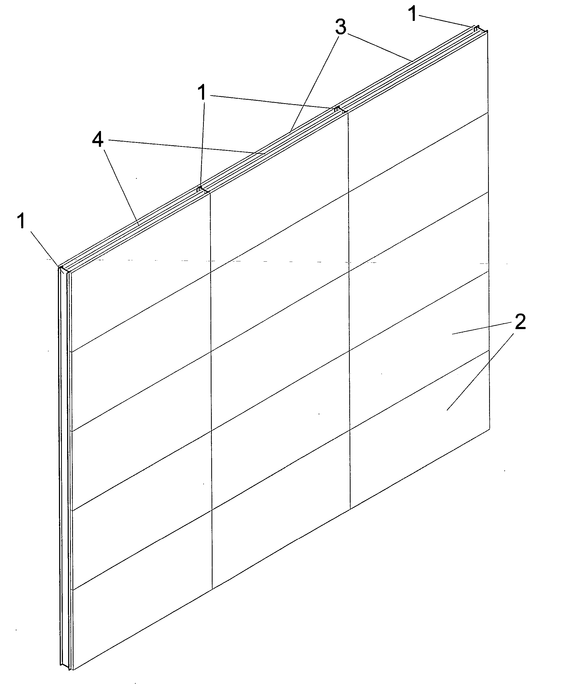
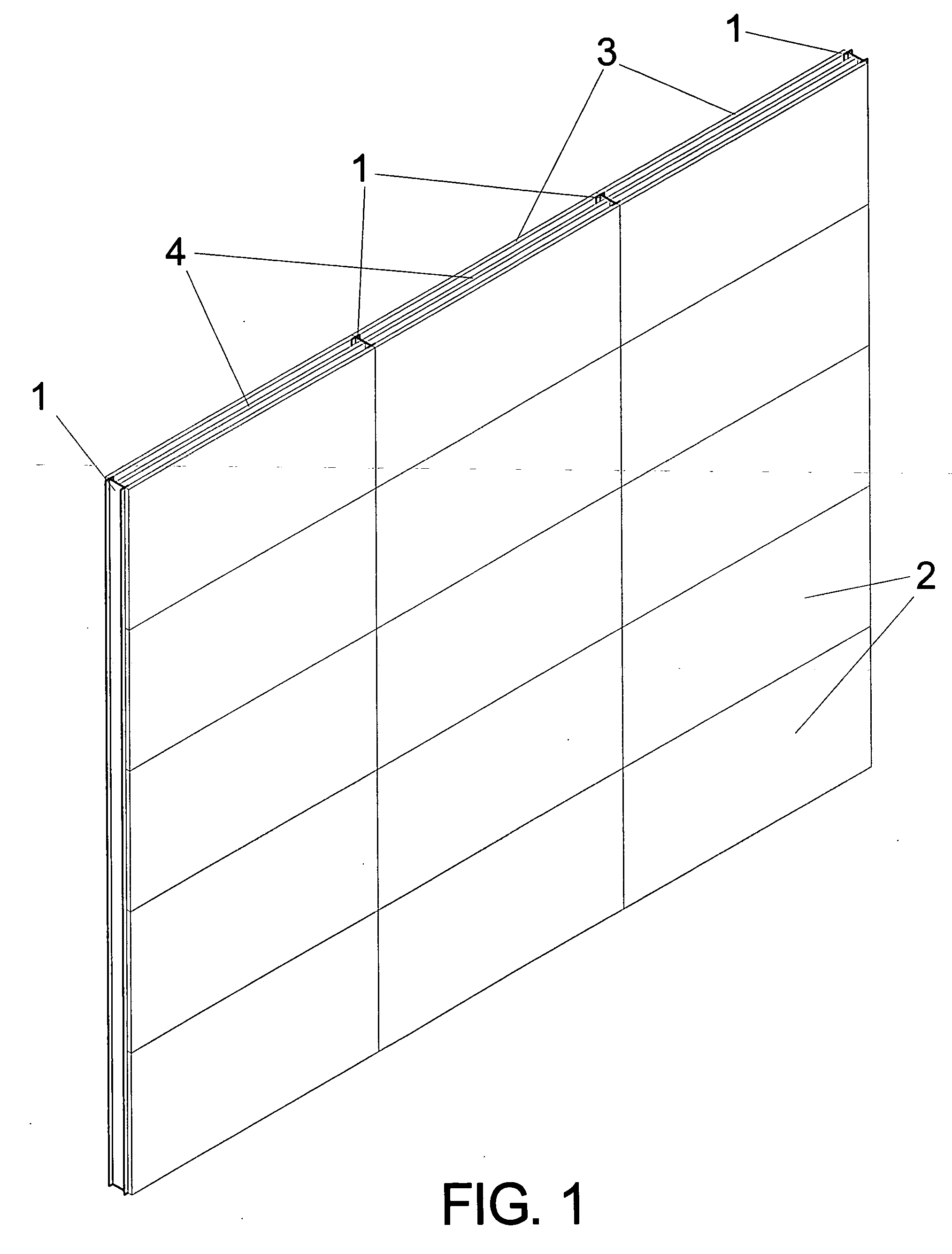
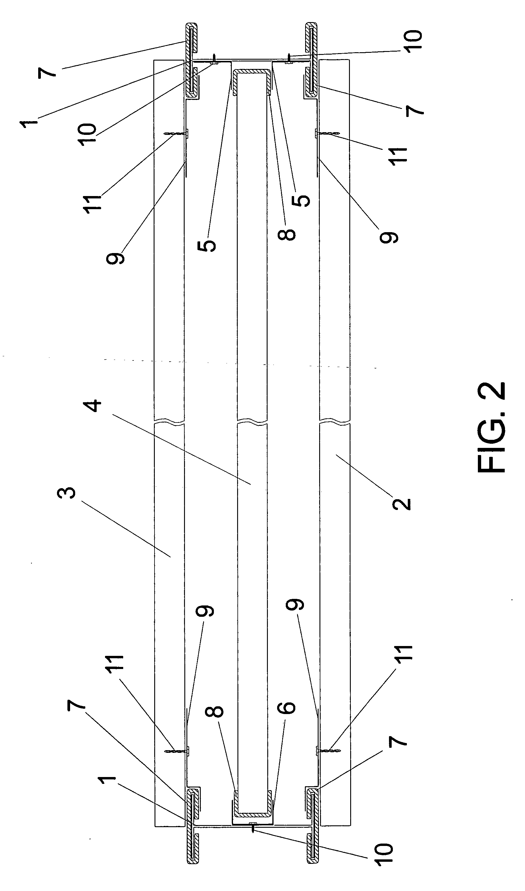
[0025] The improved construction disclosed herein includes a number of individual components, but is generally designed around a compressed straw panel. In the preferred embodiment, compressed straw panels such as those manufactured by Durra Building Systems of Texas are used. Each compressed straw panel is composed of highly compressed straw, typically wheat, rice, oat or other recovered agricultural straw lined on all exterior sides by paper or paperboard. Compressed straw panels are typically made through a dry extrusion process wherein straw is compressed into a substantially flat continuous web, normally between 1″ and 3″ thick and between 30″ and 65″ wide. As previously mentions, the continuous web is lined on all sides by paper or paperboard. The continuous web is then cut into rectangular panels of various lengths. FIG. 5 is an isometric composite view of a simple compressed straw panel 2 showing the compressed straw fibers 12 and the paperboard liner 13. The compressed stra...


PUM


Abstract

A sound insulating wall construction for improving acoustics in commercial buildings, theaters and the like having a multi-layer construction formed from at least three compressed strawboard panels in adjacent and generally parallel planar alignment and defining spaces in between which can be hollow or filled with insulating medium. Each panel is held in place by opposed edge bracket assemblies positioned to clasp the ends of each panel. The bracket assemblies include a resilient material acting to isolate or decouple each panel. The strawboard panels are positioned so that horizontal panel to panel joints in each layer are offset to eliminate easy burn through areas. Edge brackets are generally mounted to vertical I-beams and can be adapted for use with a variety of beam types.

Description

BACKGROUND OF THE INVENTION [0001] 1. Field of the Invention [0002] This invention relates to methods and structures for constructing walls which have specific acoustic characteristics, such as theater and auditorium walls. [0003] 2. Background of the Invention [0004] The primary function of interior walls and partitions is to divide building space into separate, private spaces. Many other factors, however, must be considered by designers and builders, one of which is sound control. In hotels, for example, the prevention of sounds originating in one room from passing through walls and into adjacent rooms is of major concern. This consideration is extremely important in the design and construction of multi-screen movie theaters or home media rooms. [0005] Conventional wall construction techniques tend to rely on a stud frame interior with wall covering panels comprised of gypsum board, plywood or other largely modular panels. Interior walls in offices, hotels and the like are typical...

Claims


Application Information

Patent Timeline
Patent Type & Authority Applications(United States)
IPC IPC(8): E04B9/00E06B3/54
CPCE04B2/7409E04B2/7412E04B2/7414E04B2/7457E04B2002/7464
Inventor BURG, JOHN PARKER
Owner STRAWMEN
Why Eureka
Try Eureka