Hydrogen-oxygen production device

a technology of hydrogen-oxygen and production device, which is applied in the direction of electrochemical generators, machines/engines, mechanical apparatuses, etc., can solve the problems of fossil fuel production, pollution of fossil fuel vehicles, and limited supply of fossil fuels, so as to reduce emissions and improve engine performan

Inactive Publication Date: 2006-08-17
MONETTE GREGORY R
View PDF28 Cites 32 Cited by
  • Summary
  • Abstract
  • Description
  • Claims
  • Application Information

AI Technical Summary

Benefits of technology

[0006] In order to reduce emissions and improve engine performance, a system for supplying power with a combustion engine includes a combustion engine having a fuel intake line, an air intake line, and an exhaust line. The fuel intake line receives fuel from a fuel source and the air intake line receives filtered air from an air source. The fuel can be diesel or regular gasoline. The combustion engine has a combustion chamber volume defining a predetermined number of liters of engine displacement. A hydrogen-oxygen fuel cell has a gas outlet in fluid communication with the air intake line. The hydrogen-oxygen fuel cell selectively produces hydrogen and oxy

Problems solved by technology

There are two major problems in the operation of fossil fueled vehicles that have existed for some time.
The first is the apparently limited supply of fossil fuels.
The second is the pollution that these vehicles produce.
One of the key concerns of conservation is the cost of the particular measure.
The second problem centers on the emissions produced when burning fossil fuels.
Vehicles burning such fuels often produce carbon monoxide, nitrous oxides, sulfur dioxide and other noxious gasses.
Despite these advantages, hydrogen has one serious drawback—it is highly explosive.
Thus, it has not proved practical to opera

Method used


Image

  • Hydrogen-oxygen production device
  • Hydrogen-oxygen production device
  • Hydrogen-oxygen production device

Examples


Embodiment Construction

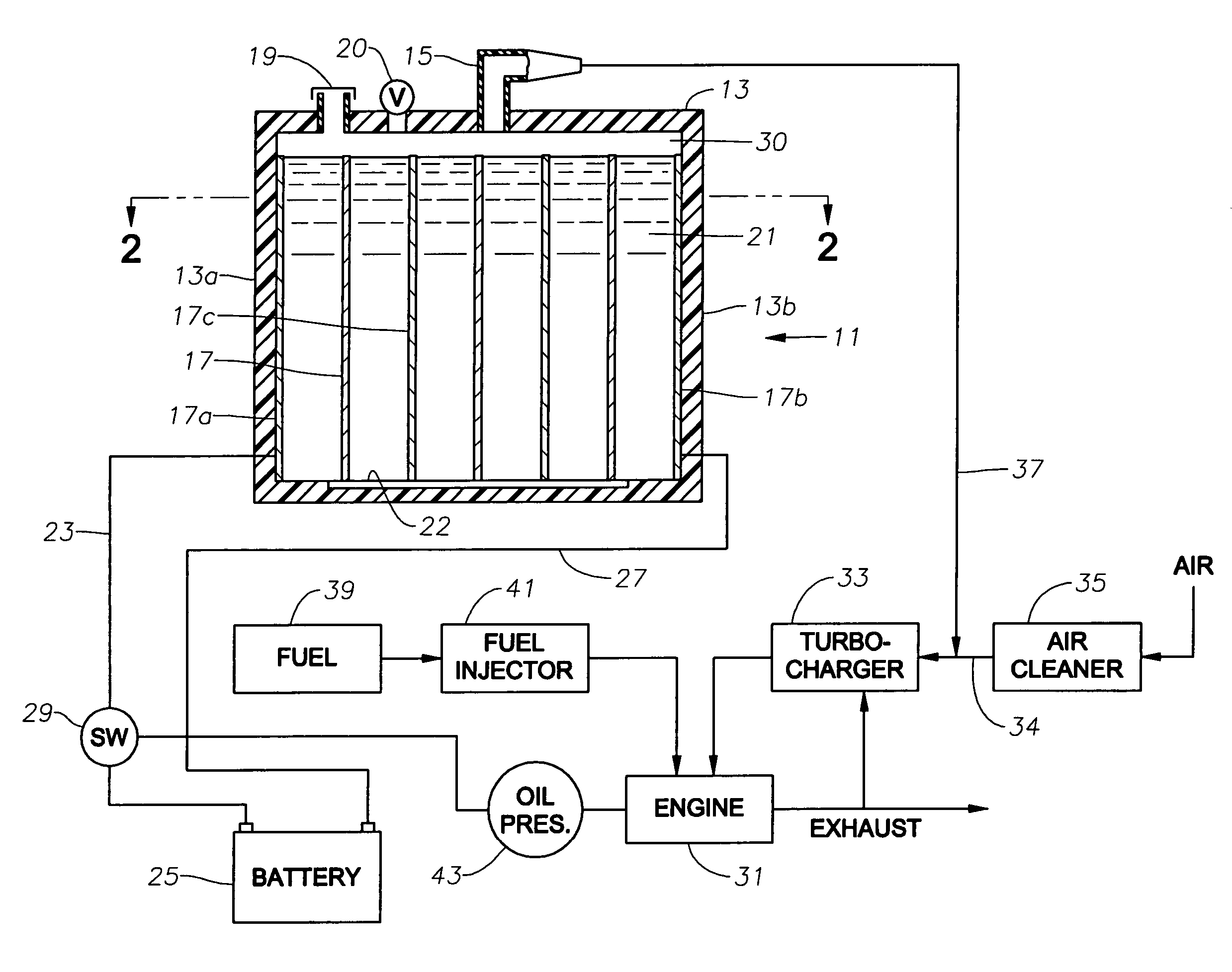
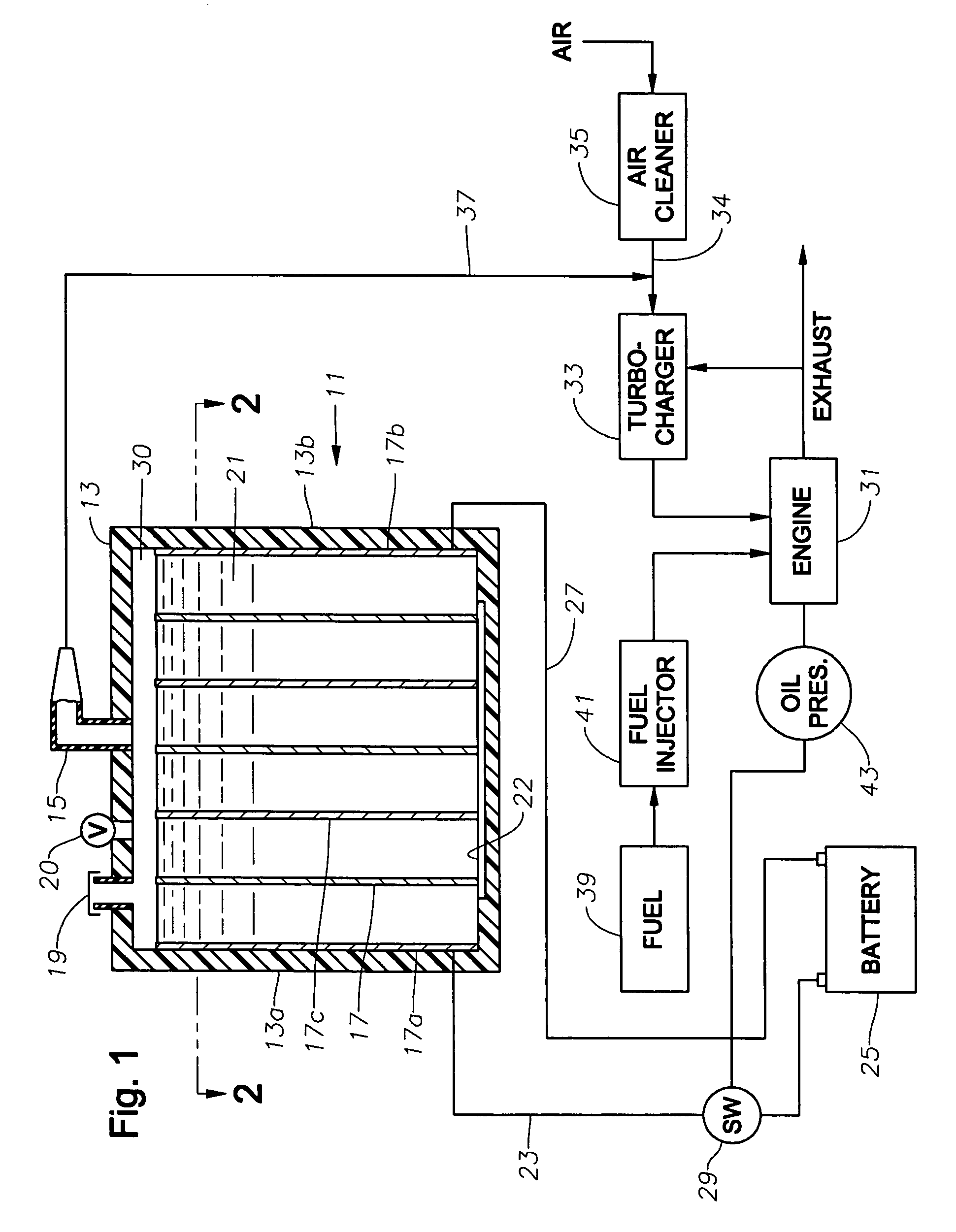
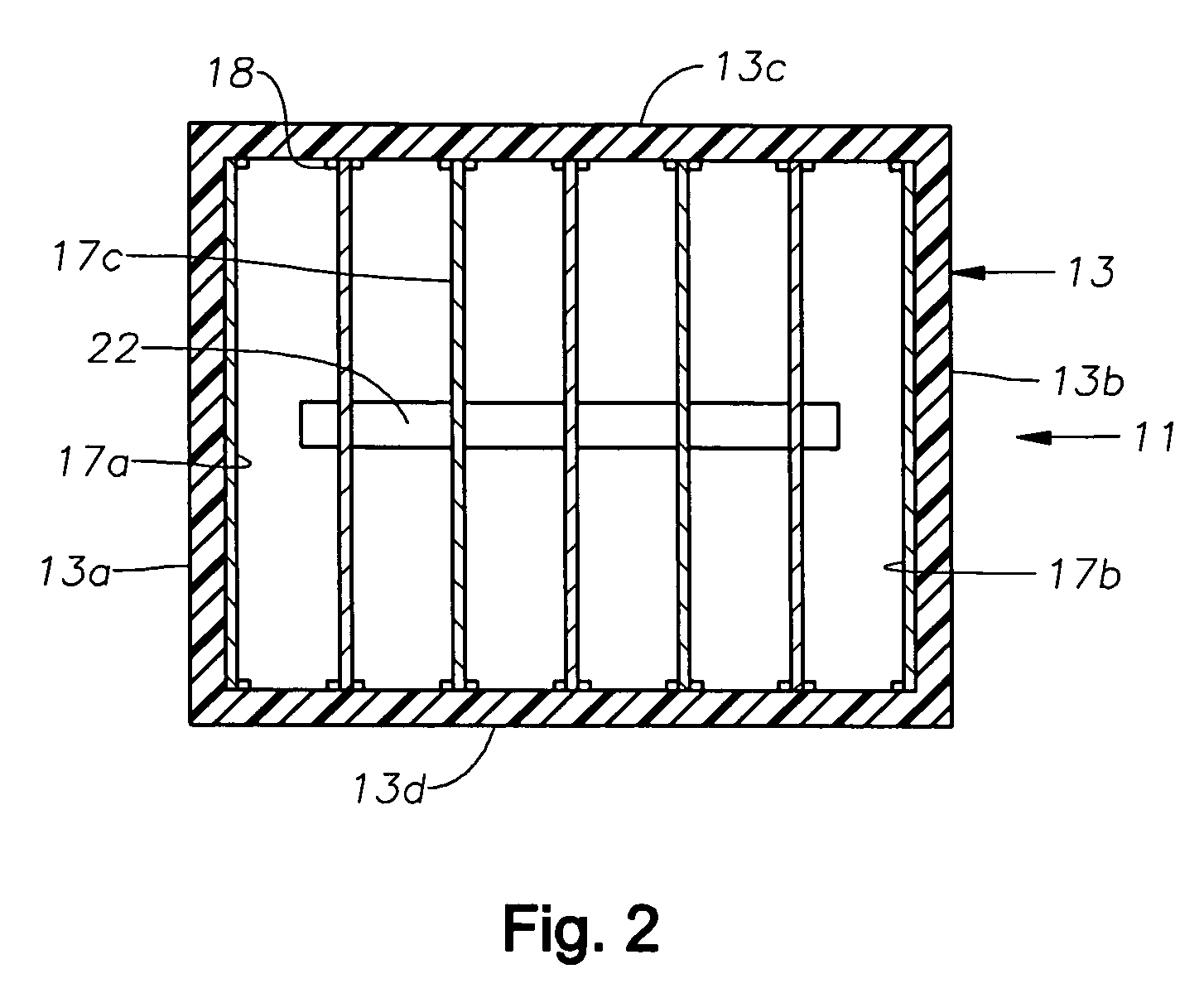
[0013] Hydrogen-oxygen generator 11 has a housing 13 preferably constructed of a durable plastic material. Housing 13 is preferably generally rectangular, having four orthogonal sidewalls 13a, 13b, 13c and 13d, as shown in FIG. 2. Housing 13 has a closed top 16 and an outlet port 15 at its top 16.

[0014] A number of electrically conductive plates 17 are mounted in housing 11 parallel to each other and equally spaced apart in the preferred embodiment. Each plate 17 is preferably of stainless steel and substantially identical to the other plates. Referring to FIG. 2, plates 17 are parallel to housing sidewalls 13a, 13b and perpendicular to sidewalls 13c, 13d. Vertical edges of plates 17 extend into slots in insulated retainers 18 on the inner sides of housing sidewalls 13c, 13d. If the material of housing 13 is a good electrical insulator, retainers 18 may be integrally formed with sidewalls 13c, 13d.

[0015] Referring again to FIG. 1, the upper edges of plates 17 are spaced a short di...


PUM


Abstract

A system for supplying power with a combustion engine includes an engine having fuel and air intake lines, and an exhaust line. The engine has a combustion chamber volume defining a number of liters of engine displacement. A fuel cell has a gas outlet that communicates with the air intake line, and selectively produces hydrogen and oxygen gases through an electrolysis process. An oil pressure sensor communicates with the engine to sense when the engine is operating. A switch communicates with the sensor and is closed when the sensor senses that the engine is operating. The switch is open when the sensor senses that the engine is not operating. A battery communicates with the fuel cell and selectively supplies electrical power for the electrolysis process when the switch is closed.

Description

1. FIELD OF THE INVENTION [0001] This invention relates in general to devices for producing hydrogen and oxygen for injection into engines powered by gasoline or diesel. 2. BACKGROUND OF THE INVENTION [0002] There are two major problems in the operation of fossil fueled vehicles that have existed for some time. The first is the apparently limited supply of fossil fuels. The second is the pollution that these vehicles produce. Even if the supply of fossil fuels expands, it is still good policy to conserve as much as practical. One of the key concerns of conservation is the cost of the particular measure. So, the ideal conservation measure is one that produces significant reductions in fuel use at the lowest possible cost. [0003] The second problem centers on the emissions produced when burning fossil fuels. Vehicles burning such fuels often produce carbon monoxide, nitrous oxides, sulfur dioxide and other noxious gasses. These products are a result, in part, of engines not completely...

Claims


Application Information

Patent Timeline
IPC IPC(8): F02B43/08
CPCF02B37/00F02B43/10F02B2043/106F02D19/081F02M25/12H01M8/186H01M16/003H01M2250/407Y02E60/563Y02T10/121Y02T10/36Y02T10/32F02D19/0644F02D19/0671Y02E60/50Y02T10/12Y02T10/30
Inventor MONETTE, GREGORY R.
Owner MONETTE GREGORY R
Why Eureka
Try Eureka