Motor system for vehicle

a technology for motor systems and vehicles, applied in the direction of braking systems, electric devices, propulsion by batteries/cells, etc., can solve the problems of large motors, unsuitable voltage supply for motors in unsprung parts, and large motors, so as to improve vehicle mobility (running performance), reduce unsprung loads, and improve vibration resistance

Inactive Publication Date: 2006-08-17
HITACHI LTD
View PDF22 Cites 38 Cited by
  • Summary
  • Abstract
  • Description
  • Claims
  • Application Information

AI Technical Summary

Benefits of technology

[0013] According to the present invention, a motor system for a vehicle can be made small and light and vibration resistance can be improved.
[0014] Furthermore, according to the present invention, the unsprung load can be reduced and vehicle mobility (running performance) can be improved.
[0015] Still furthermore, according to the present invention, the number of wire harnesses used for connections between the sprung part and the unsprung part can be reduced.

Problems solved by technology

As a result, the motor disposed in the unsprung part is not supplied with an adequate voltage.
To cope with the problem, it has been unavoidable to design a motor to be operable with a low voltage and a large current, eventually making the motor large.
Secondly, as each drive circuit for wheel is disposed in the sprung part, turning on and off the drive circuit generates electromagnetic noise in AC harness connecting the drive circuit and the corresponding motor.
This increases the unsprung load, thereby decreasing resistance to vibration and lowering suspension performance.

Method used


Image

  • Motor system for vehicle
  • Motor system for vehicle
  • Motor system for vehicle

Examples


first embodiment

[0027] A configuration of a motor system for a vehicle according to the present invention will be described with reference to FIGS. 1 to 5. Described in the following by way of an example is a motor system for a vehicle applied to an electric brake.

[0028] First, an overall configuration of a vehicle equipped with the motor system for a vehicle according to the present embodiment will be described with reference to FIGS. 1 and 2.

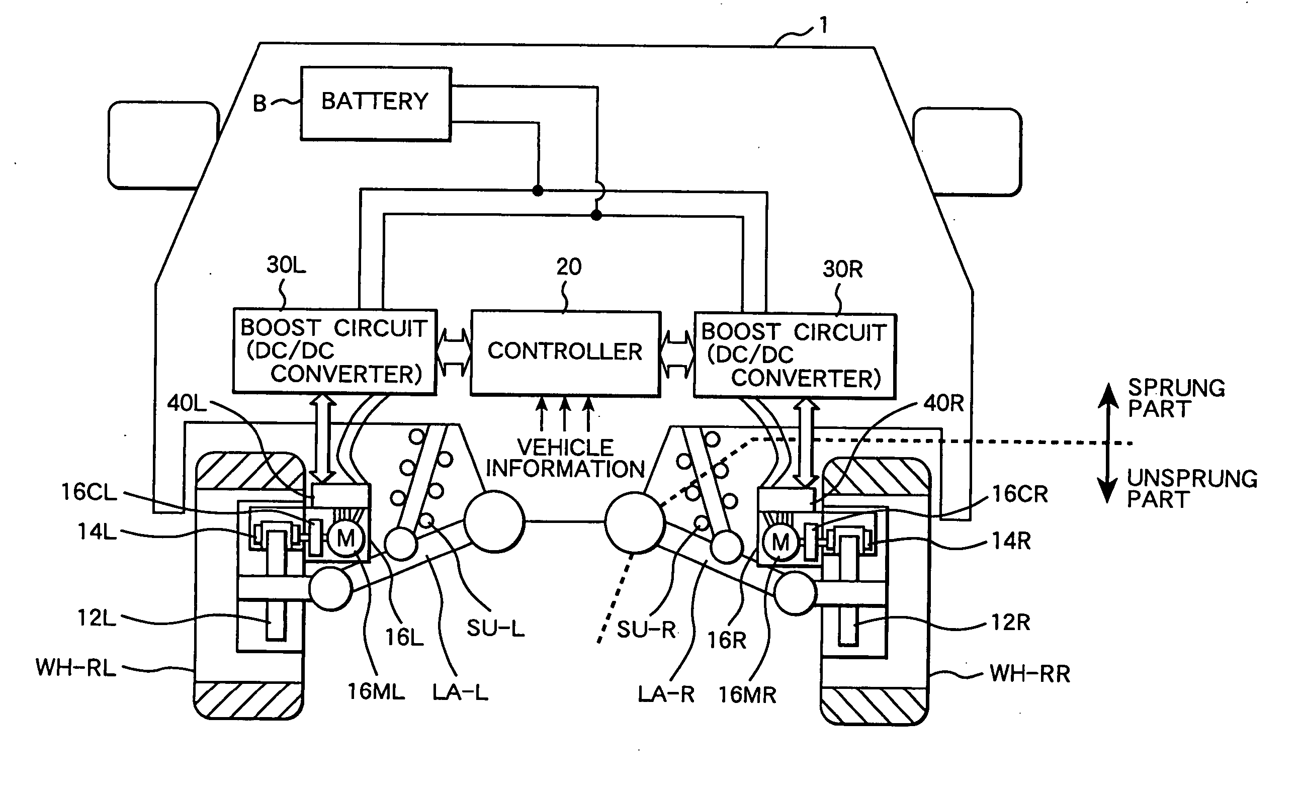
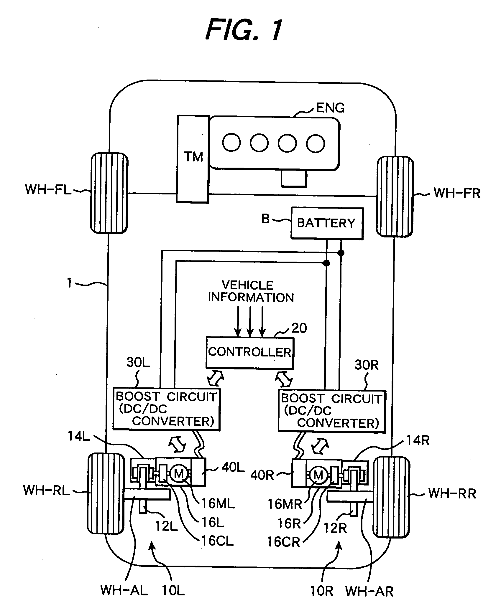
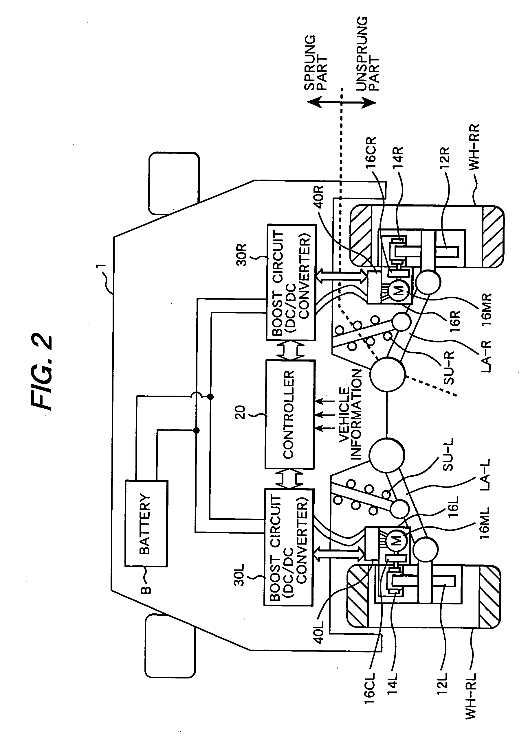
[0029]FIG. 1 is a system block diagram showing, in a planar state, an overall configuration of a vehicle equipped with the motor system for a vehicle according to the first embodiment of the present invention. FIG. 2 is a block diagram showing, in a sectional state, an overall configuration of the vehicle equipped with the motor system for a vehicle according to the first embodiment.

[0030] As shown in FIG. 1, a vehicle 1 includes two front wheels WH-FR and WH-FL and two rear wheels WH-RR and WH-RL. The driving force of an engine ENG is transmitted to the fr...

second embodiment

[0055] Next, with reference to FIGS. 6 to 9, a configuration of a motor system for a vehicle according to the present invention will be described. Described in the following by way of an example is a motor system for a vehicle applied to an electric brake.

[0056] First, an overall configuration of a vehicle equipped with the motor system for a vehicle according to the present embodiment will be described with reference to FIGS. 6 and 7.

[0057]FIG. 6 is a system block diagram showing, in a planar state, an overall configuration of a vehicle equipped with the motor system for a vehicle according to the second embodiment. FIG. 7 is a block diagram showing, in a sectional state, an overall configuration of the vehicle equipped with the motor system for a vehicle according to the second embodiment. Of the reference numerals and letters used in FIGS. 6 and 7, those which are the same as reference numerals and letters used in FIGS. 1 and 2 denote the same parts as shown in FIGS. 1 and 2.

[0...

third embodiment

[0068] Next, with reference to FIGS. 10 and 11, a configuration of a motor system for a vehicle according to the present invention will be described. Described in the following by way of an example is a motor system for a vehicle including in-wheel motors which are drive motors built into rear wheels. Even though, in the present example, the front wheels of a vehicle are driven by an engine with each of the rear wheels being a wheel with a built-in motor, the configuration being described in the following can be used also in a case where all of the four wheels are provided with in-wheel motors.

[0069]FIG. 10 is a system block diagram showing, in a planar state, an overall configuration of a vehicle equipped with the motor system for a vehicle according to the third embodiment of the present invention. FIG. 11 is a block diagram showing, in a sectional state, an overall configuration of the vehicle equipped with the motor system for a vehicle according to the third embodiment of the p...


PUM


Abstract

Motors are disposed in an unsprung part of the vehicle with reference to a suspension. Drive circuits which rectangular-wave drive the motors are disposed in the unsprung part. Voltage control circuits which control voltage supplied from a battery to the drive circuits are disposed in the sprung part of the vehicle with reference to the suspension. The motors are three-phase synchronous motors.

Description

CLAIM OF PRIORITTY [0001] The present application claims priority from Japanese application serial no. 2005-36400, filed on Feb. 14, 2005, the content of which is hereby incorporated by reference into this application. BACKGROUND OF THE INVENTION [0002] The present invention relates to a motor system for a vehicle. More particularly, it relates to a motor system for a vehicle with the motor disposed unsprung part with reference to suspensions in a vehicle. [0003] The motor system for a vehicle, having suspensions between a car body and wheels and motors as rotary electric machine for vehicle disposed in an unsprung part of the vehicle, is known conventionally. Such known motor systems for vehicles are provided as: an electric parking brake and an electric brake disclosed in Japanese Patent Laid-Open No. 2004-122838 and Japanese Patent Laid-Open No. 2004-90774; and a system for producing a driving force (a so-called in-wheel motor) for an electric car or a hybrid car as disclosed in ...

Claims


Application Information

Patent Timeline
Patent Type & Authority Applications(United States)
IPC IPC(8): B60K1/00
CPCB60K7/0007B60K2007/0038B60K2007/0061B60K2007/0092B60L11/123B60L2220/14B60L2220/44B60L2220/46B60T13/741Y02T10/6217Y02T10/646Y02T10/7005Y02T10/7077Y02T10/648B60L50/61Y02T10/62Y02T10/70Y02T10/64Y02T10/7072
Inventor INNAMI, TOSHIYUKISATO, HIROYUKIKADOMUKAI, YUUZOUYASUKAWA, DAISUKEKURAMOCHI, YUICHIMIYAZAKI, HIDEKI
Owner HITACHI LTD
Why Eureka
Try Eureka