Elevator installation with a braking device and method for braking and holding an elevator installation

a technology for elevators and braking equipment, which is applied in the direction of braking systems, lifts, track-braking member co-operation, etc., can solve the disadvantage of increasing the speed in the case of fully laden cars, significant transient process, and insufficient braking equipment for holding elevator cars in a stopped position. , to achieve the effect of low power consumption, low cost and low cos

Active Publication Date: 2006-08-17
INVENTIO AG
View PDF12 Cites 54 Cited by
  • Summary
  • Abstract
  • Description
  • Claims
  • Application Information

AI Technical Summary

Benefits of technology

[0008] An object of the present invention is accordingly to provide regulatable braking equipment and a method for braking and holding an elevator car, which enables retardation or holding in correspondence with the operational state of the elevator installation and responds quickly and in gentle manner. The braking equipment must, in addition, fulfill high safety demands and it shall be able to be operated with lower power and have little additional weight. The susceptibility of the braking equipment to fault shall, moreover, be low.

Problems solved by technology

A disadvantage of this equipment is that the brake equipment is not designed for holding an elevator car in a stopped position, such as, for example, at a regular stop at a floor.
In addition, the braking equipment is set to a fixed value which is predetermined by the spring and which in the working case is either moved towards as quickly as possible, which leads to a significant transient process, or which in the working case is moved towards slowly, controlled by the counter-force of the stroke magnets, whereby the speed in the case of a fully laden car disadvantageously increases.
Moreover, the regulatable magnet is expensive and heavy, it additionally absorbs a large amount of power, and monitoring of the operational readiness of the equipment can be difficult to carry out.
A disadvantage of this equipment is that relevant influencing factors, which influence the braking force, are not recognized and not taken into consideration.
A defect of a spring, wear of a brake lining or jamming of brake levers can lead to a relevant influencing of the braking force, which is not recognized.
These disadvantages potentially increase the susceptibility to fault in the case of installation and in the case of replacement as well as in operation; hence the brake-specific characteristics of each brake unit have to be input at the brake control unit.

Method used


Image

  • Elevator installation with a braking device and method for braking and holding an elevator installation
  • Elevator installation with a braking device and method for braking and holding an elevator installation
  • Elevator installation with a braking device and method for braking and holding an elevator installation

Examples


Embodiment Construction

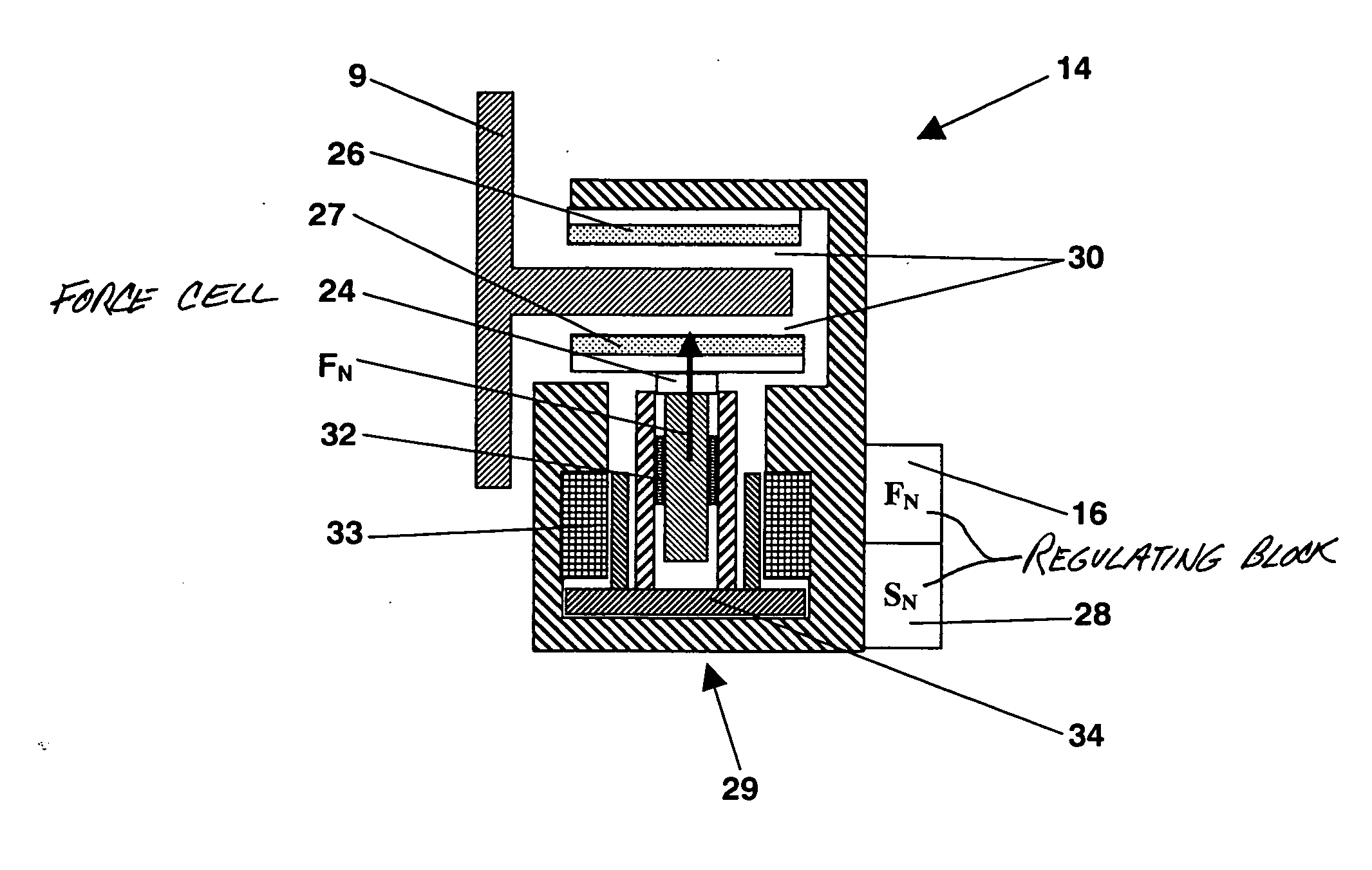
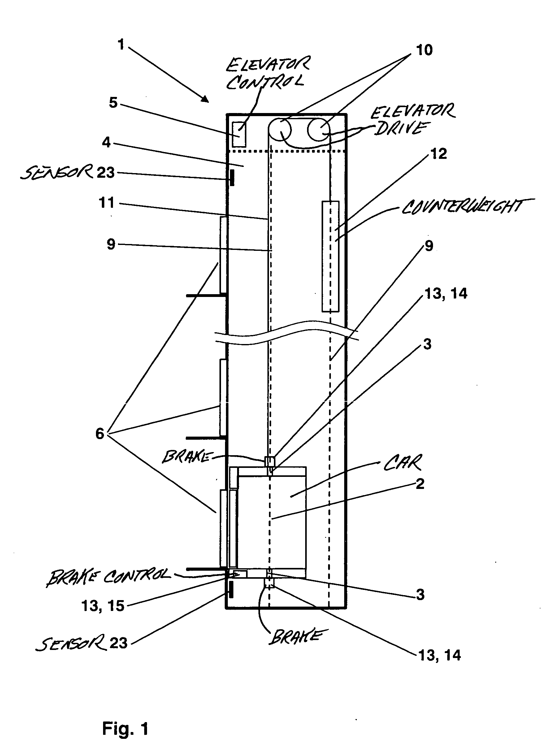
[0023] An elevator installation 1 consists at least of an elevator car 2 and an elevator drive 10. As illustrated in FIG. 1, the elevator installation 1, for example, further requires a support means 11 and a counterweight 12, wherein the elevator drive 10 drives the support means 11 and thus moves the elevator car 2 and the counterweight 12 in diametrical opposition in an elevator shaft 4. The elevator installation 1 also requires at least one braking equipment 13. The braking equipment 13 holds the stationary elevator car 2—for example, during the loading time at a floor 6—or it brakes the elevator car 2 in an emergency situation—for example, in the case of unexpected opening of the floor access—or it effects safety braking—for example, in the case of failure of the support means 11—of the elevator car 2 which is moving too fast. These different load cases require different braking or holding forces FB.

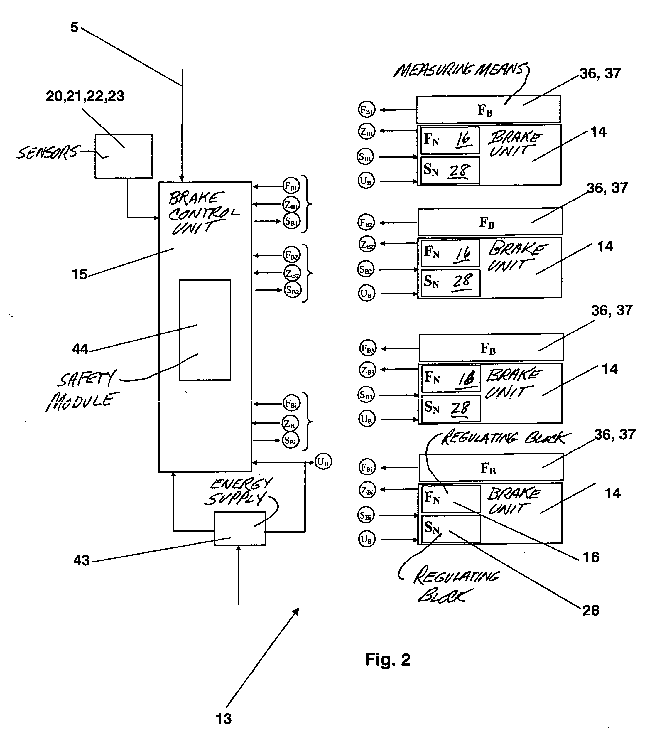
[0024]FIG. 2 shows a variant of the braking equipment 13, which consists of a ...


PUM


Abstract

An elevator installation has braking equipment for braking and holding an elevator car which moves in vertical direction within guide tracks or rails. The braking equipment consists of at least two brake units each comprising a normal force regulation device that sets a normal force (FN) in correspondence with a normal force value determined by a brake control unit and/or a locking device that locks the brake unit in a set braking position and which preferably maintains the set braking position in the case of an interrupted energy supply. The braking equipment provides a gentle braking or holding of the elevator car, which corresponds with the operational state of the elevator installation, with a low energy requirement.

Description

BACKGROUND OF THE INVENTION [0001] The present invention relates to an elevator installation with braking equipment and to a method for braking and arresting an elevator installation. [0002] An elevator installation comprises an elevator car which moves in a vertical direction within guide tracks or guide rails. The elevator car is in the case of need braked or held at standstill by braking equipment. For holding or braking the elevator car a braking force is required. The braking equipment for that purpose usually utilizes at least two brake units which when required press at least one brake lining against a counter-surface. This pressing is effected by means of a normal force. The braking force of a brake lining is determined by the normal force together with the coefficient of friction defined by the brake lining, the counter-surface and any intermediate layers. The counter-force is usually defined by a surface of the guide track or the guide rail. [0003] German patent DE 3934495...

Claims


Application Information

Patent Timeline
Patent Type & Authority Applications(United States)
IPC IPC(8): B66B5/16
CPCB66B1/32B66B5/16B66B1/24B66B1/28
Inventor GREMAUD, NICOLASGRUNDMANN, STEFFENKOCHER, HANS
Owner INVENTIO AG
Why Eureka
Try Eureka