Expansion-type reflection mirror

a reflection mirror and expansion-type technology, applied in the field of deployable reflectors, can solve the problems of limiting the inability to maintain the shape of the antenna reflection surface, and the inability to obtain predetermined shapes merely by a single adjustment, so as to reduce the degree of distortion of the reflector surface, reduce the degree of deformation of the polyhedral shape, and suppress the variation of the length of the internal surface cable system

Inactive Publication Date: 2006-08-17
NIPPON TELEGRAPH & TELEPHONE CORP
View PDF5 Cites 23 Cited by
  • Summary
  • Abstract
  • Description
  • Claims
  • Application Information

AI Technical Summary

Benefits of technology

[0022] If it is rendered in a tense state by the deployable truss structure, the integrated system of cables constituting the reflector surface of the deployable reflector assumes a polyhedral shape that is uniquely determined by the lengths of the three sides of each of the triangles of the internal surface cable system. In this state, suppressing variations in the lengths of the internal surface cable system makes it possible to reduce the degree of deformation of the polyhedral shape that approximates a reflector surface and to thereby reduce the degree of distortion of the reflector surface.
[0023] With the configuration of this invention, since the circumferential surface cable system is made of a cable that is low in stiffness and is small in the ratio of the tension variation to the length variation, displacements of the de

Problems solved by technology

However, the payload shroud of a rocket is restricted.
Therefore, the predetermined shape cannot be obtained merely by a single adjustment.
Incidentally, the integrated system of cables 100 of the conventional deployable reflectors is made of a pliable, flexible cable and cannot maintain an antenna reflection surface shape on its own.
However, to increase the stiffness of the deployable truss structure 106, it is necessary to make the individual members constituting the deployable truss thicker, which raises a problem of increase in total weight.
In particular, since the back cable system is made of a cable that is high in stiffness and is small in the ratio of the length variation to the tension variation from the viewpoint of ease of adjustment, slight variations in the positions of the stand-offs cause large tension variations.
The tension variations of the individual cable sections in a balanced state cause length variations of the surface cable

Method used


Image

  • Expansion-type reflection mirror
  • Expansion-type reflection mirror
  • Expansion-type reflection mirror

Examples


Embodiment Construction

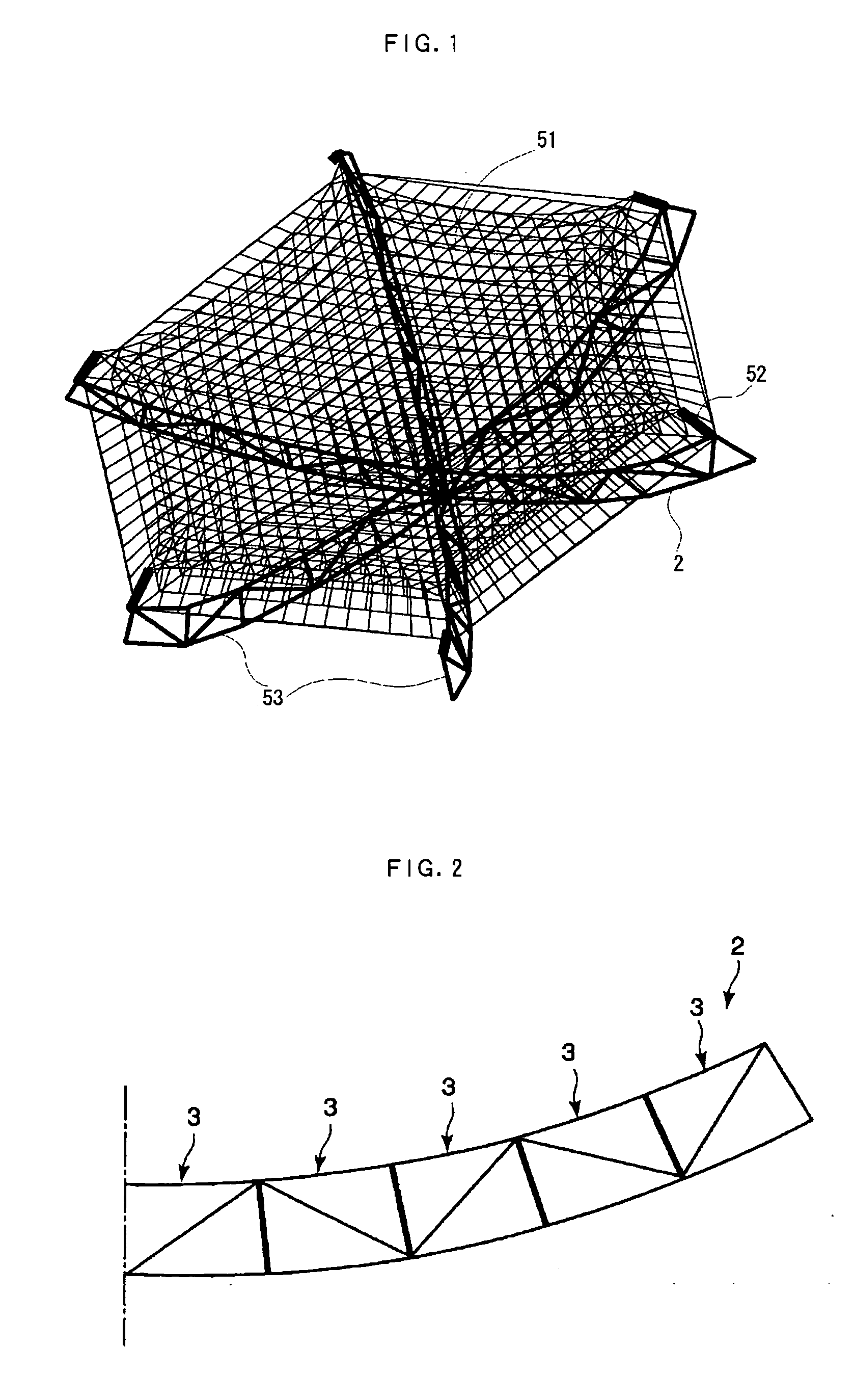
[0050]FIG. 1 is a perspective view showing the configuration of a deployable reflector (1) according to the invention. As shown in the figure, in this deployable reflector, a surface shape is formed in such a manner that an integrated system of cables 51 is stretched on a deployable truss structure 53 via stand-offs 52. For example, where the integrated system of cables 51 having a predetermined shape is used as a reflector of a large deployable antenna to be mounted on a communication satellite, the reflector surface assumes a parabolic shape and radio waves are sent and received by an antenna feeder (not shown) that is installed at the focal point position.

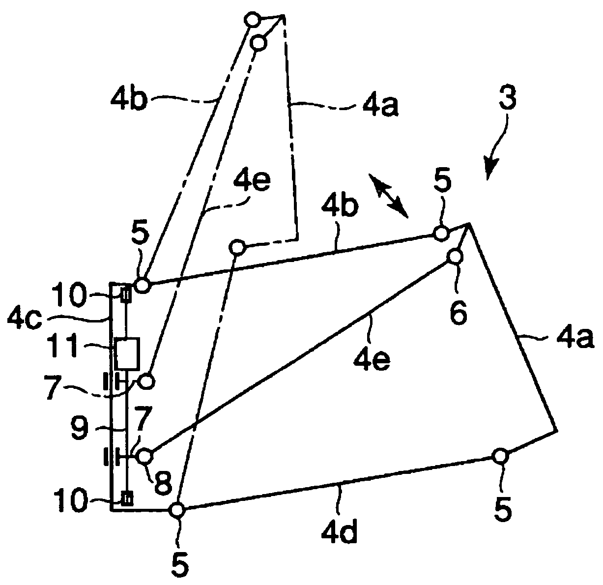
[0051] In the deployable truss structure 53, plural (in this example, six) frames 2 (extendable structures) are arranged radially by connecting their proximal portions to each other. The thus-configured deployable truss structure 53 can be folded or deployed with the proximal portions as the rotating point. The deployable truss...


PUM


Abstract

A deployable reflector of the invention includes connection members that bridge plural extendable structures constituting a deployable truss structure and connect portions corresponding to nodes of a buckling mode occurring in the extendable structures when a surface cable system is given tension, with portions corresponding to antinodes thereof. The surface cable system includes an internal surface cable system and a circumferential surface cable system connected to the outer circumference thereof. A cable used for the internal surface cable system is high in stiffness and small in ratio of length variation to tension variation. A cable used for the circumferential surface cable system is lower in stiffness and smaller in ratio of the tension variation to the length variation than that used for the internal surface cable system. Given tension by the deployable truss structure via the circumferential surface cable system, the internal surface cable system forms predetermined surface shape.

Description

TECHNICAL FIELD [0001] The present invention relates to a deployable reflector that is mounted on an artificial satellite or the like in a folded state and is deployed in space. In particular, the invention relates to a deployable reflector that has a small volume in a folded state and assumes a predetermined shape in a deployed state. BACKGROUND ART [0002] To transport a deployable antenna mounted on an artificial satellite or the like to space, a rocket such as an Ariane rocket, or H-IIA is used as a transporting unit. However, the payload shroud of a rocket is restricted. Therefore, to transport a large deployable antenna, it is accommodated in a rocket in a small, folded state and is deployed after the rocket reaches space. Among deployable reflectors constituting such a deployable antenna, exemplified is one that is a combination of plural fundamental structures and can form a large deployable antenna depending on the number of fundamental structures. [0003]FIG. 13 shows the co...

Claims


Application Information

Patent Timeline
IPC IPC(8): G02B5/08G02B7/182G02B7/183H01LH01Q1/28H01Q15/16H01Q15/20
CPCG02B7/183H01Q1/288H01Q15/162
Inventor HARADA, SATOSHIMEGURO, AKIRAISHIKAWA, HIRONORIOZAWA, SATORU
Owner NIPPON TELEGRAPH & TELEPHONE CORP
Why Eureka
Try Eureka