
Vehicular mirror device

Inactive Publication Date: 2006-08-17
HONDA LOCK MFG CO LTD
View PDF7 Cites 3 Cited by
  • Summary
  • Abstract
  • Description
  • Claims
  • Application Information

AI Technical Summary

Benefits of technology

[0009] With the arrangement of the first feature, the part of the operating shaft that couples the operating shaft to the mirror holder moves, in response to swing of the mirror holder, in a direction along the straight line linking the part of the drive shaft that couples the drive shaft to the mirror holder, the fulcrum of the mirror holder, and the part of the operating shaft that couples the operating shaft to the mirror holder. Therefore, the operating shaft swings around an axis that is perpendicular to a plane containing the above-mentioned straight line. However, since the detection rod has the axis coaxial with the swing axis of the operating shaft and is coupled to the operating shaft so that the operating shaft can swing around the swing axis, the position of the detection rod can be stably maintained at a position corresponding to the axial position of the operating shaft regardless of swing of the operating shaft within the guide hole. Thus, it is possible to stabilize the accuracy of the sensor in detecting the axial position of the operating shaft, thereby enhancing the accuracy of the sensor in detecting the swing angle of the mirror holder.
[0011] With the arrangement of the second feature, when the tip of the detection rod is fitted into and coupled to the other end part of the operating shaft, the operating shaft can be axially pushed against the detection rod in a state in which the detection rod is made stationary by making the tip abut against the stopper, and in this process, since the tip of the detection rod is received by the stopper, no bending stress is exerted on the detection rod from the operating shaft side. Furthermore, also when abnormal external force acts on the mirror holder and the operating shaft moves beyond a specified value, since the tip of the detection rod is received by the stopper, no bending stress is exerted on the detection rod. Therefore, both in a case in which the tip of the detection rod is fitted into and coupled to the other end part of the operating shaft, and a case in which the operating shaft moves beyond a specified value, it is possible to prevent a bending stress from acting on the detection rod, thus reliably preventing deformation of the detection rod, and thereby avoiding a degradation in the detection accuracy of the sensor.
[0013] With the arrangement of the third feature, by pushing the operating shaft against the detection rod in a state in which it is received by the stopper, the operating shaft can guide the tip of the detection rod smoothly from the guide part to the mating part and fit it into the mating part while elastically deforming so as to widen the width of the channel part, and the tip of the detection rod can easily be fitted into and coupled to the other end part of the operating shaft.
[0015] With the arrangement of the fourth feature, within the case main body, the first housing part housing the drive means and the first lid member covering the first housing part may have substantially the same shape as that of an actuator case of a vehicular mirror device having a function of only driving the mirror holder by visual remote operation. When molding the first lid member, by sharing and using a mold for molding the actuator case of the vehicular mirror device having the function of only driving the mirror holder by visual remote operation, the cost can be reduced. Moreover, since the first housing part housing the drive means and the second housing part housing the sensor are coupled as a unit via the coupling part, component precision control and adjustment can be made easy, and the number of assembly steps can be decreased.

Problems solved by technology

Therefore, in this conventional structure in which the sensor is fixedly disposed in an attitude at an inclination of 45 degrees relative to the straight line, a force is exerted on the detection rod of the sensor from a direction at an inclination of 45 degrees, so that the position of the detection rod becomes uncertain, and consequently the accuracy of detection of the axial position of the operating shaft by the sensor becomes unstable, thus resulting in a deteriorated accuracy of the sensor in detecting the swing angle of the mirror holder.

Method used


Image

  • Vehicular mirror device
  • Vehicular mirror device
  • Vehicular mirror device

Examples


Embodiment Construction

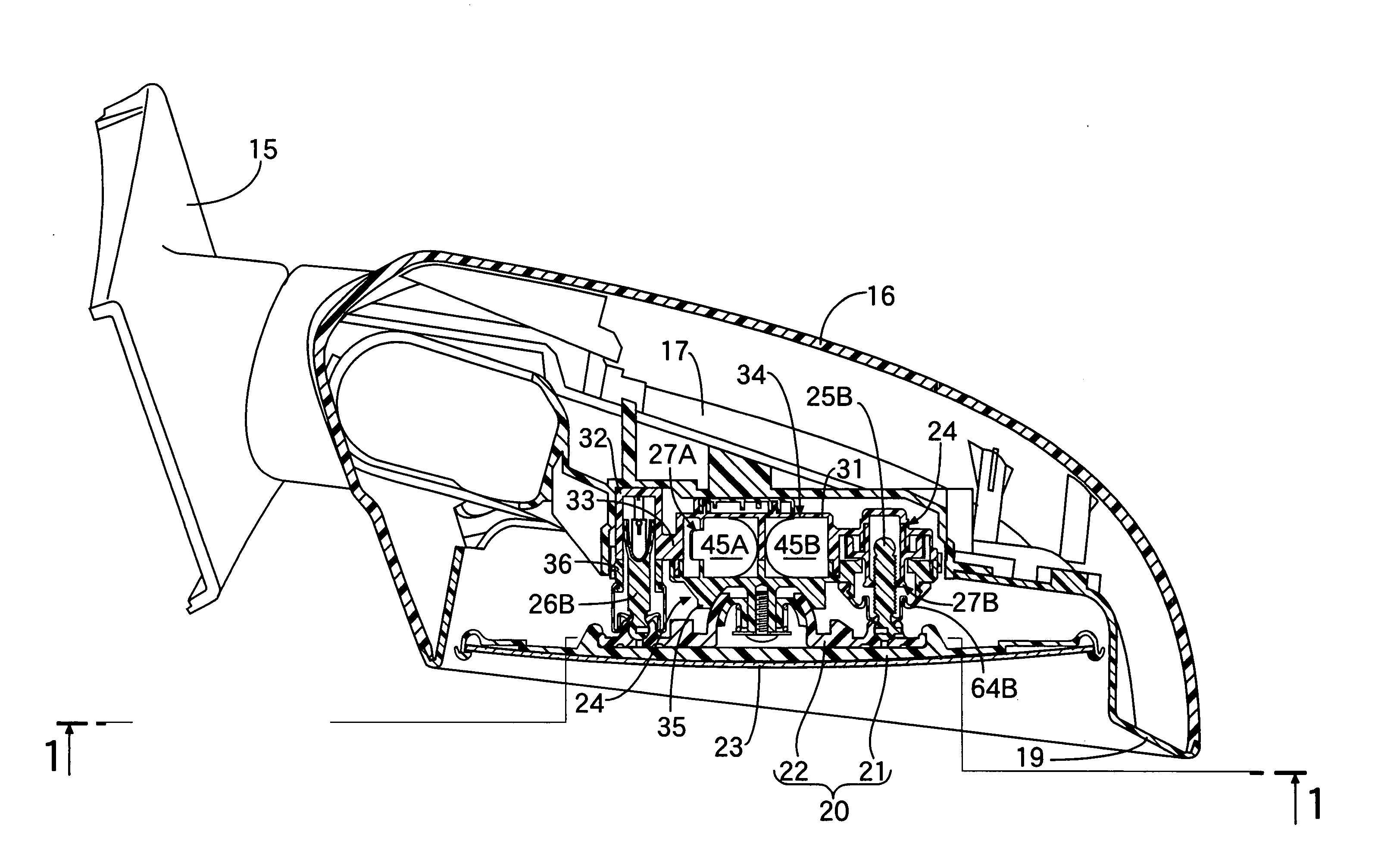
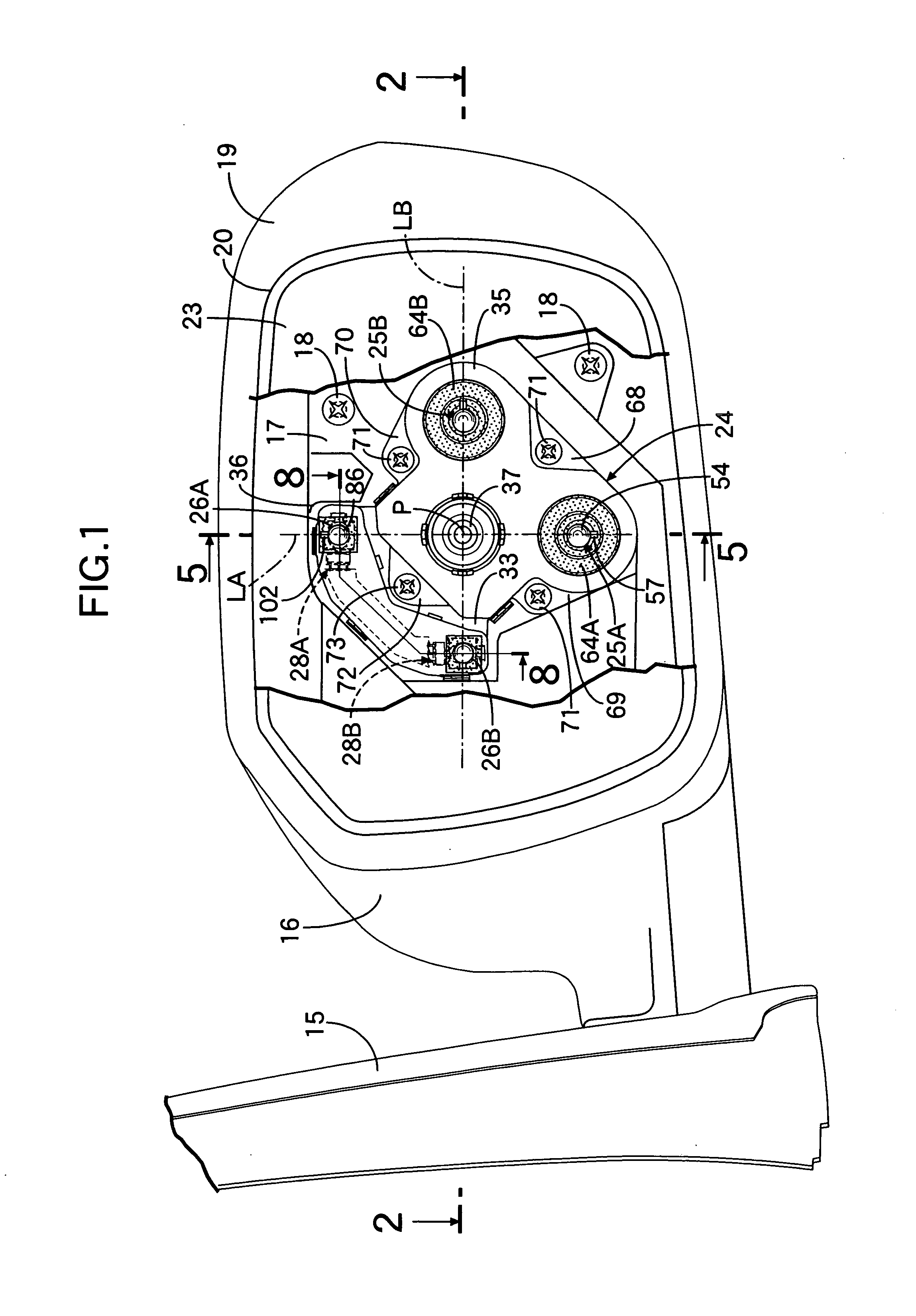
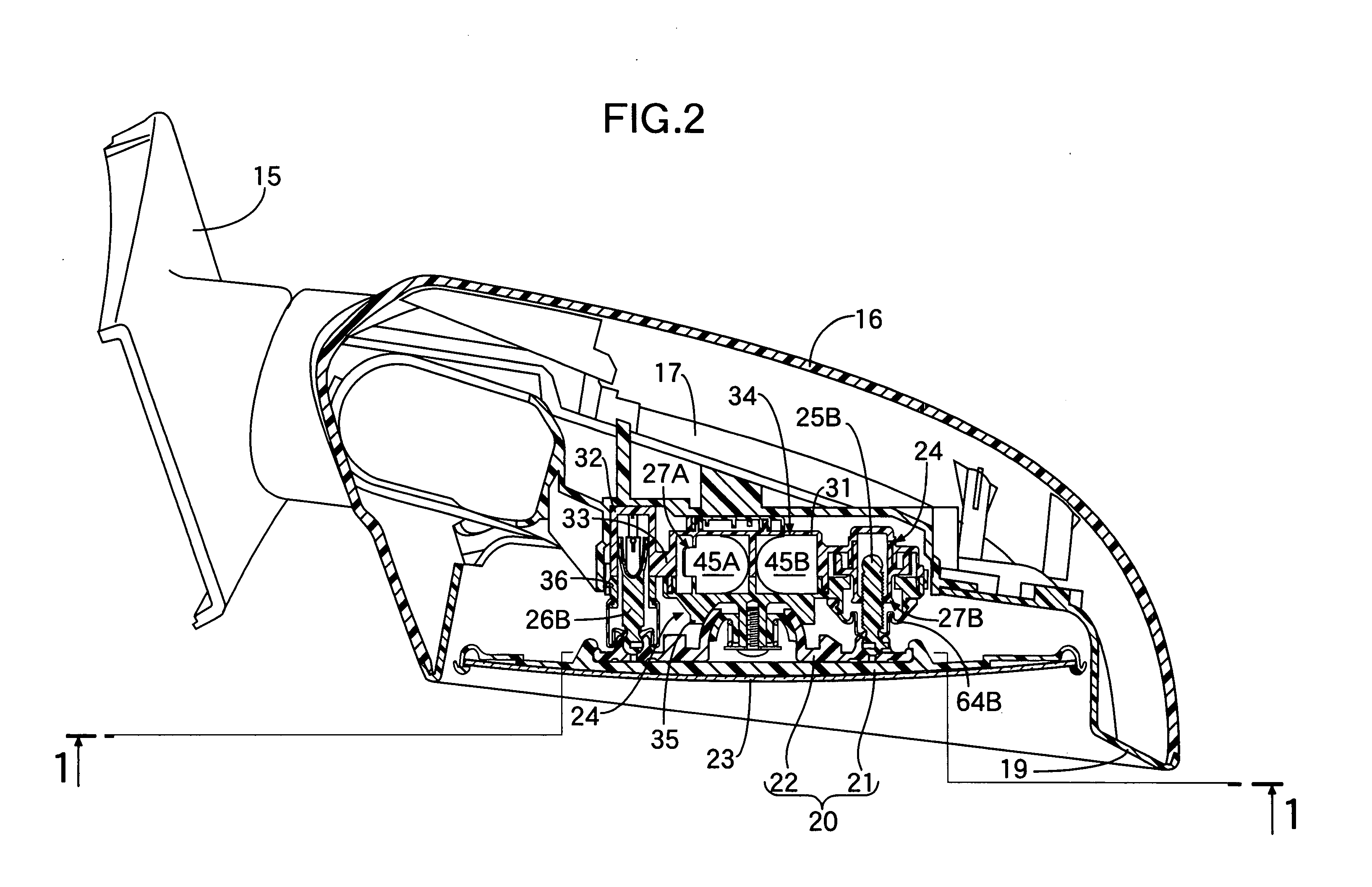
[0028] One embodiment of the present invention is described below in reference to FIG. 1 to FIG. 11; referring first to FIG. 1 and FIG. 2, a base 15 is mounted on a side door of a vehicle, and a synthetic resin housing 16 is pivotably supported on the base 15 so that it can pivot to the front and rear of the vehicle.

[0029] A synthetic resin bracket 17 is pivotably supported on the base 15. The housing 16, which covers the bracket 17, is mounted on the bracket 17 via a plurality of screw members 18. A peripheral edge part of a visor 19 extending within the housing 16 and mounted on the housing 16 is connected to an open edge of the housing 16. A mirror 23 held by a mirror holder 20 is disposed within the visor 19 so as to enable viewing toward the rear of the vehicle.

[0030] The mirror holder 20 is formed from a holder main part 21 and an inner holder 22 fixed to an inner face side of the holder main part 21, the mirror 23 being mounted on an outer face side. The mirror holder 20 is...


PUM


Abstract

In a vehicular mirror device, one end part of an operating shaft disposed on a side opposite to a drive shaft relative to a fulcrum of a mirror holder is swivelably coupled to the mirror holder, and a detection rod of a sensor is coupled to the operating shaft, which is slidably inserted into a guide hole provided in a fixed support member, so that it detects a swing angle of the mirror holder according to an axial position of the operating shaft. The operating shaft is inserted into the guide hole while being supported on the support member so that it can swing around an axis perpendicular to a plane containing a straight line linking a part of the drive shaft that couples the drive shaft to the mirror holder, the fulcrum of the mirror holder, and a part of the operating shaft that couples the operating shaft to the mirror holder. The detection rod, which has an axis coaxial with the swing axis of the operating shaft, is coupled to the operating shaft so that the operating shaft can swing around the swing axis. Thus, the swing angle of the mirror holder can be detected with a high accuracy.

Description

RELATED APPLICATION DATA [0001] The present invention is based upon Japanese priority application Nos. 2005-36470, 2005-36471 and 2005-36472, which are hereby incorporated in their entirety herein by reference. BACKGROUND OF THE INVENTION [0002] 1. Field of the Invention [0003] The present invention relates to a vehicular mirror device in which an axially movable drive shaft is coupled to a mirror holder swingably supported by a fulcrum disposed on a straight line perpendicular to the axis of the drive shaft, one end part of an operating shaft disposed on the straight line on a side opposite to the drive shaft relative to the fulcrum is swivelably coupled to the mirror holder, and a detection rod of a sensor fixed to a fixed support member is coupled to the operating shaft, which is slidably inserted into a guide hole provided in the support member so as to extend parallel to the drive shaft, so that it detects a swing angle of the mirror holder according to an axial position of the...

Claims


Application Information

Patent Timeline
IPC IPC(8): G02B7/182
CPCB60R1/072
Inventor ISHIKAWA, KAORU
Owner HONDA LOCK MFG CO LTD
Learn More