Optical pickup and optical disk device

a technology of optical disk and optical pickup, which is applied in the direction of mountings, instruments, data recording, etc., can solve the problems of disadvantageous to miniaturization realization, disadvantageous to reducing power consumption, disadvantageous to reducing parts cost and/or assembly cost, etc., and achieves reducing parts cost and/or assembling cost, the effect of reducing power consumption

Inactive Publication Date: 2006-08-17
SONY CORP
View PDF0 Cites 9 Cited by
  • Summary
  • Abstract
  • Description
  • Claims
  • Application Information

AI Technical Summary

Benefits of technology

[0009] An object of the present invention is to provide an optical pick-up which solves the problems that conventionally proposed optical pick-up devices as described above have, which realizes miniaturization and is advantageous to reduction of power consumption, and which is advantageous to reduction of parts costs and / or assembling cost, and an optical disc apparatus using such an optical pick-up.

Problems solved by technology

This is disadvantageous to realization of miniaturization.
This is disadvantageous to reduction of power consumption.
This is disadvantageous to reduction of parts cost and / or assembling cost.

Method used


Image

  • Optical pickup and optical disk device
  • Optical pickup and optical disk device
  • Optical pickup and optical disk device

Examples


first embodiment

[0028] Initially, an optical pick-up according to the present invention and an optical disc apparatus using such an optical pick-up will be explained.

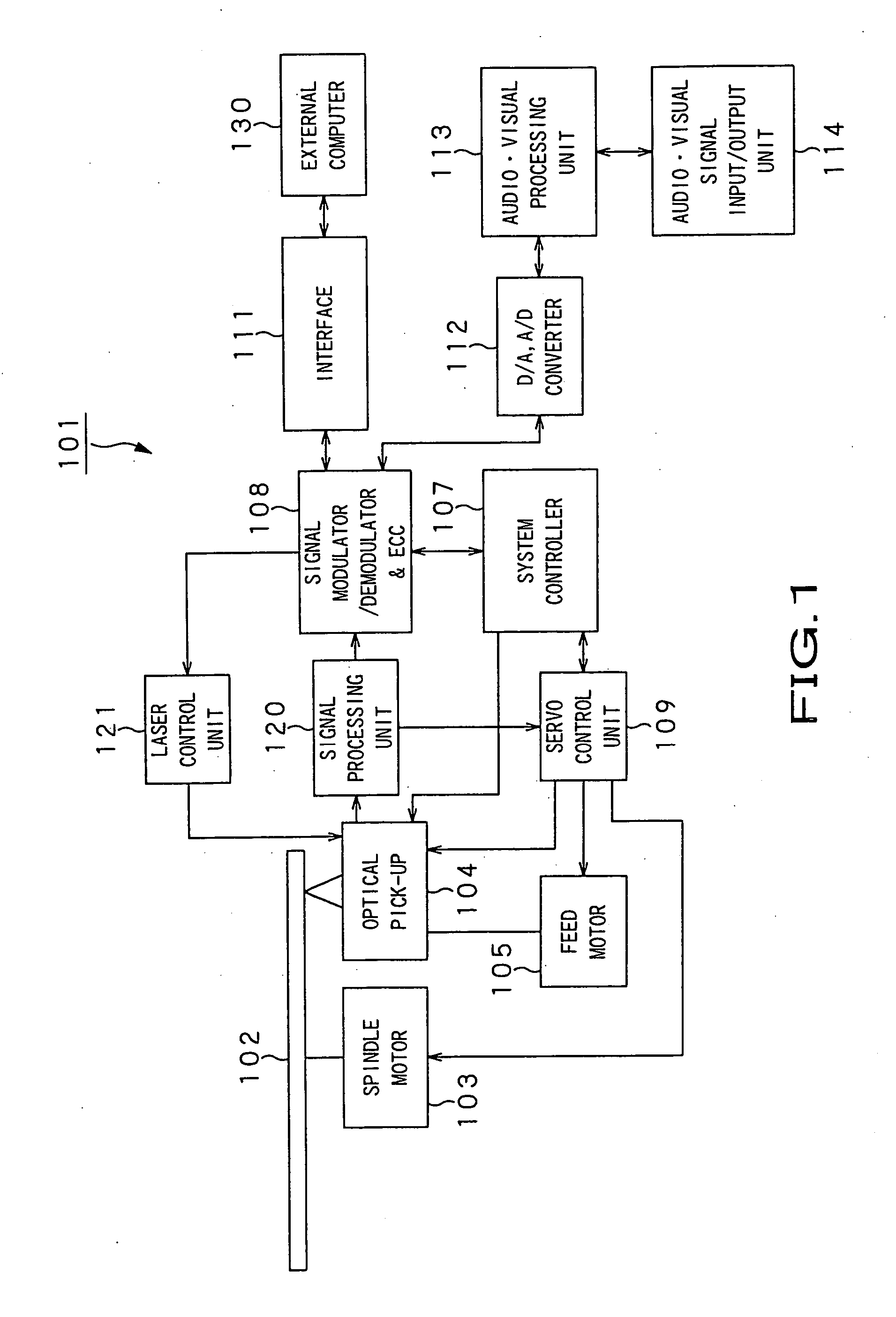
[0029] The optical disc apparatus in which the optical pick-up to which the present invention is applied is assembled has a configuration as shown in FIG. 1.

[0030] The optical disc apparatus 101 to which the present invention is applied comprises, as shown in FIG. 1, a spindle motor 103 serving as drive means for rotationally driving an optical disc 102 as a light recording medium such as CD-R, DVD±R, DVD-RAM, etc., an optical pick-up 104, and a feed motor 105 serving as drive means for driving the optical pick-up 104 in the radial direction thereof. Here, the spindle motor 103 is controlled so that it is driven at a predetermined number of rotations by a system controller 107 and a servo control unit 109.

[0031] A signal modulating / demodulating unit (modulator / demodulator) and ECC block 108 performs modulation / demodulation of signals...

second embodiment

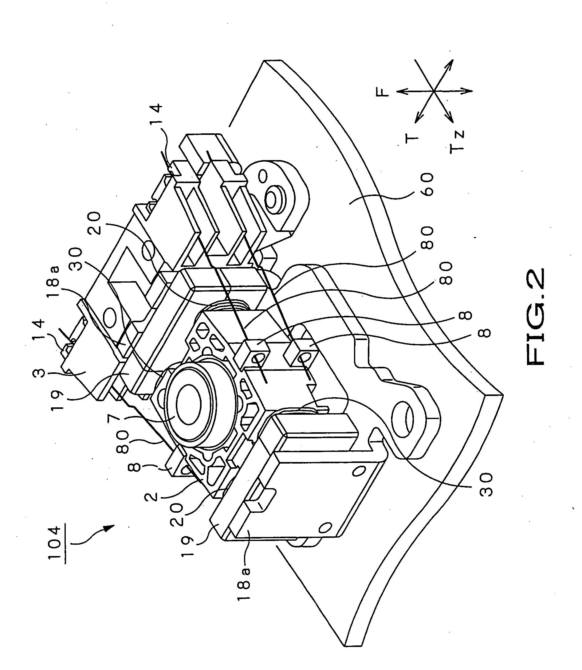
[0089] Then, the optical pick-up of the present invention will be explained.

[0090] The second embodiment different from the previously described first embodiment in the arrangement of the focus coil and the tracking coil.

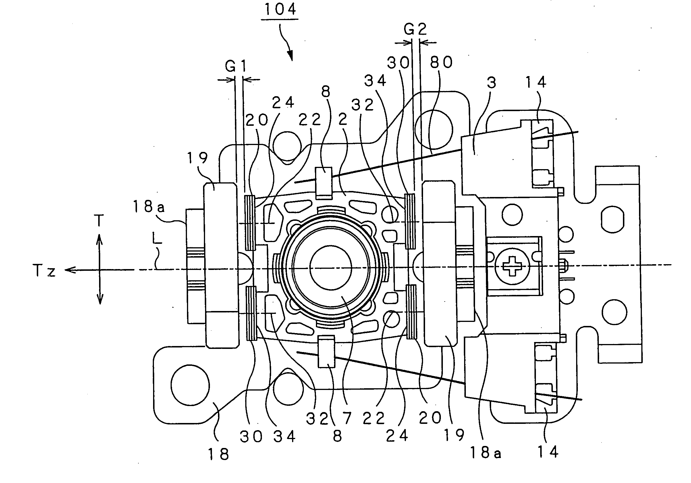
[0091]FIG. 7 is a front view showing the configuration of arrangement of the focus coil and the tracking coil of the optical pick-up according to the second embodiment.

[0092] In the following explanation, common reference numerals are respectively attached to portions common to the previously described first embodiment, and the detailed explanation will be omitted.

[0093] In the optical pick-up according to this embodiment, as shown in FIG. 7, the supporting arms 80 are formed from a pair of left supporting arms 802 and a pair of right supporting arms 804 which are extended in the tangential direction in the state positioned at both sides of the object lens 7. The pair of left supporting arms 802 and the pair of right supporting arms 804 are respectively disposed ...

third embodiment

[0104] The optical pick-up 304 is used for an optical disc apparatus in which plural kinds of optical discs where plural kinds of light beams having wavelengths different from each other are selectively used so that recording or reproduction of information signals is performed are selectively used as recording media. As an optical disc apparatus of this kind, there is an optical disc apparatus in which there are used, as recording media, e.g., a first optical disc where light beams having wavelength of 400 to 410 mm are used so that recording or reproduction of information signals is performed, a second optical disc where light beams having wavelength of 650 to 660 nm are used so that recording or reproduction of information signals is performed, and a third optical disc where light beams having wavelength of 760 to 800 nm are used so that recording or reproduction of information signals is performed.

[0105] At the optical pick-up 304 used for the optical disc apparatus in which plu...


PUM

PropertyMeasurementUnit
tilt angleaaaaaaaaaa
wavelengthaaaaaaaaaa

Abstract

The present invention is directed to an optical pick-up adapted for moving an object lens (7) supported by a lens holder (2) in a focus direction in parallel to the optical axis direction thereof and in a tracking direction perpendicular to the focus direction, and for performing control of tilt angle serving to tilt the optical axis of the object lens following inclination of an optical disc. At the lens holder, there are provided a pair of focus coils (20) and a pair of tracking coils (30). The pair of focus coils have coil surfaces which are perpendicular to winding axes of coil portions constituting the respective focus coils and face magnets, and are so attached to the lens holder as to face the tangential direction with the object lens put therebetween, the pair of focus coils being shifted in left and right directions respectively away from a virtual axis which is perpendicular to the tracking direction and passes along the optical axis of the object lens, the coil surfaces being directed toward the tangential direction. By changing a drive force produced at the pair of focus coil portions, tilt angle of the object lens is controlled.

Description

TECHNICAL FIELD [0001] The present invention relates to an optical pick-up used for performing recording of information signals onto an optical disc and for performing reproduction of information signals recorded on an optical disc, and an optical disc apparatus using such an optical pick-up. [0002] This application claims priority of Japanese Patent Application No. 2004-145482, filed on May 14, 2004, and Japanese Patent Application No. 2004-311892, filed on Oct. 27, 2004, the entireties of which are incorporated by reference herein. [0003] Hitherto, as recording media for information signals, there are used optical discs such as CD (Compact Disc) or DVD (Digital Versatile Disc), etc. In order to perform recording of information signals onto an optical disc, and to perform reproduction of information signals recorded on an optical disc, there is used an optical pick-up. [0004] Such optical pick-up comprises a biaxial actuator for moving an object lens in a focus direction which is t...

Claims


Application Information

Patent Timeline
Patent Type & Authority Applications(United States)
IPC IPC(8): G11B7/00G11B7/085G11B7/09G11B7/095
CPCG11B7/08582G11B7/0956G11B7/093G11B7/08G11B7/085G11B7/09G11B7/095
Inventor MIYAGI, TAKAHIRO
Owner SONY CORP
Why Eureka
Try Eureka