System and method for sharpening vector-valued digital images

a digital image and vector-value technology, applied in the field of image data processing, can solve the problems of image quality, other undesirable artifacts, difficulty in further processing that image, etc., and achieve the effect of increasing noise, increasing noise, and increasing nois

Inactive Publication Date: 2006-08-17
SOZOTEK
View PDF7 Cites 22 Cited by
  • Summary
  • Abstract
  • Description
  • Claims
  • Application Information

AI Technical Summary

Benefits of technology

[0015] It is an aspect of the present invention to provide a method for sharpening multi-spectral digital images without increasing noise through filtering vector values rather than independent scalar values.
[0016] It is another aspect of the present invention to provide a system for sharpening multi-spectral digital images without increasing noise.
[0017] These and other aspects, features, and advantages are achieved according to the method and system of the present invention. In accordance with the present invention, sharpening multi-spectral digital images without increasing noise is accomplished by filtering vector values rather than independent scalar values. A low-pass filter is performed on an original image A to obtain a blurred image B1 with noise and signal suppressed. The resulting blurred image B1 is subtracted from image A to produce a high frequency band C1 that contains noise and signal. Vector difference mean filtering is performed on the original image A to produce a filtered image B2 with noise suppressed. The filtered image B2 is subtracted from image A to produce a noise band C2 that contains noise with very little signal. The noise band C2 is subtracted from the high frequency band C1 to produce a signal band D that contains the signal. The signal band D is then added to the filtered image B2 to further enhance edge detail in the noise filtered band.

Problems solved by technology

The '409 application describes methods for capturing digital images by devices such as cameras and scanners, compressing those images, transmitting them to remote locations, and further processing them typically create disturbances in the images called “noise.” Such noise throughout the pixels of an image may detract from the image's quality and may cause difficulties in further processing that image to modify it for corrections, enhancements, and other changes.
These prior techniques often sharpen some image details effectively, but they also typically create other undesirable artifacts in the images.
However, when a digital image is noisy, sharpening techniques may increase noise undesirably. FIG. 4 shows a representative graph of a digital image with a noisy edge.
If a high-pass filter is performed on this noisy edge and the resulting value is added back into the original image, the final sharpened image typically contains increased noise, as shown in FIG. 5.
However, prior methods such as those described in U.S. Pat. Nos. 6,373,992 and 6,055,340 for Nagao still tend to cause significant undesirable artifacts in sharpened digital images because they perform their techniques separately on independent scalar values, which are individual color bands, as explained in “System and Method for a Vector Difference Mean Filter for Noise Suppression,” cited above.
For example, filters that supply replacement values through averaging surrounding pixels in separate color areas tend to cause image distortions because they distort the balance among the separate areas of color near edges, typically causing undesirable artifacts.
In addition prior methods such as U.S. patent application 20040066850 for Nakajima typically operate on three color bands, red, green, and blue, and are not applicable to all vector-valued, multi-spectral images, which may have more than three component planes.
Moreover, technique described in U.S. patent application 20040066850 for Nakajima is computing intensive, which makes it expensive.

Method used


Image

  • System and method for sharpening vector-valued digital images
  • System and method for sharpening vector-valued digital images
  • System and method for sharpening vector-valued digital images

Examples


examples

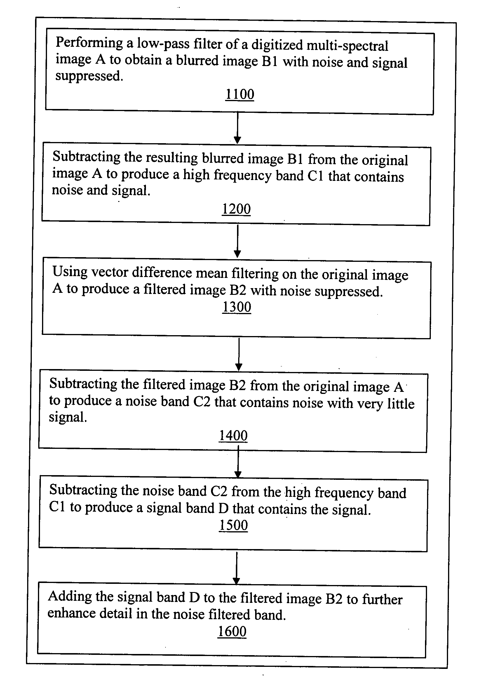
[0067] The vector difference filtering may be performed as discussed in pending application number “System and Method for a vector difference mean filter for noise suppression,” Ser. No. 10 / 992,409, cited above.

[0068] In one example, the vector values comprise a red scalar color component, a green scalar color: component, and a blue scalar component for each of the plurality of pixels in the image. In another example, there are six vector values- an amplitude of a red scalar color component, a phase of a red scalar color component, an amplitude of a green scalar color component, a phase of a green scalar color component, an amplitude of a blue scalar color component, and a phase of a blue scalar color component. In another example, there are four vector values a cyan scalar color component, a magenta scalar color component, a yellow scalar color component, and a black scalar color component value for each of the plurality of pixels a black scalar color component value for each of t...


PUM


Abstract

Sharpening multi-spectral digital images without increasing noise is accomplished by filtering vector values rather than independent scalar values. A low-pass filter is performed on image A to obtain a blurred image B1 with noise and signal suppressed. The resulting blurred image B1 is subtracted from the original image A to produce a high frequency band C1 that contains noise and signal. Vector difference mean filtering is performed on the original image A to produce a filtered image B2 with noise suppressed. The filtered image B2 is subtracted from the original image A to produce a noise band C2 that contains noise with very little signal. The noise band C2 is subtracted from the high frequency band C1 to produce a signal band D that contains the signal. The signal band D is then added to the filtered image B2 to further enhance detail in the noise filtered band.

Description

FIELD OF THE INVENTION [0001] The present invention relates generally to the field of processing image data; and more particularly to a system and method for processing multi-spectral digital images to sharpen edge details without increasing noise. BACKGROUND OF THE INVENTION [0002] This application incorporates by-reference U.S. utility patent application “System and Method for a vector difference mean filter for noise suppression,” Ser. No. 10 / 992,409, filed Nov. 18, 2004 by Mark Shulze and the current inventor, George John. In this prior patent application, reduction of noise in digitized vector-valued, multi-spectral digital images is provided by filtering based on vector values rather than independent scalar values. Vector values refer to a pixel-with two or more values. Examples of vector-valued, multi-spectral images include RGB (red, green, blue) images or amplitude, phase vectors for images such as holograms. The '409 application describes methods for capturing digital imag...

Claims


Application Information

Patent Timeline
Patent Type & Authority Applications(United States)
IPC IPC(8): G06K9/40
CPCG06T5/004
Inventor JOHN, GEORGE
Owner SOZOTEK
Why Eureka
Try Eureka