Information acquisition method, information acquisition apparatus and disease diagnosis method
a technology of information acquisition and information acquisition apparatus, which is applied in the direction of instruments, gas-filled discharge tubes, solid cathodes, etc., can solve the problems of difficult to know the original structure of the sample, difficult to obtain information, and difficulty in analyzing time, etc., to achieve excellent quantitative properties, high sensitivity, and efficient operation
- Summary
- Abstract
- Description
- Claims
- Application Information
AI Technical Summary
Benefits of technology
Problems solved by technology
Method used
Image

Examples
example 1
Production of a Chip Spotted with Synthetic Peptide
[0189] A Ti film of 5 nm was formed on a silicon substrate that was free of impurities, followed by formation thereon of an Au film of 100 nm. This silicon substrate attached with Au underwent the following treatment prior to spotting thereon of synthetic peptides as described below.
[0190] 100 μl of hydrogen peroxide solution (30% solution) was inserted into a glass beaker, 300 μl of concentrated sulfuric acid was gently dropped therein, and the resulting mixture was stirred while shaking lightly. Thereafter, the solution was heated to 80° C., and the above silicon substrate attached with Au was washed in this solution for 5 min. The substrate was subsequently taken out, carefully washed with distilled water, and air-dried.
[0191] Next, a 10 μM aqueous solution of synthetic peptide I (SEQ ID NO: 1, C21H34N10O11S (average molecular weight: 634.61; mass of molecules comprising elements having the highest isotope ratio: 634.21)) pur...
example 2
TOF-SIMS of Chip Produced in Example 1
[0193] The chip produced in Example 1 was air-dried and analyzed using the TOF-SIMS IV apparatus manufactured by ION-TOF GmbH. The measurement conditions are summarized below.
Primary ion: 25 kV Ga+, 0.6 pA (pulse current value), random scan mode
Pulse frequency of primary ion: 2.5 kHz (400 μs / shot)
Primary ion pulse width: approx. 1 ns
Primary ion beam diameter: approx. 5 μm
Field of measurement: 300 μm×300 μM
Number of pixels of secondary ion image: 128×128
Number of integrations: 256
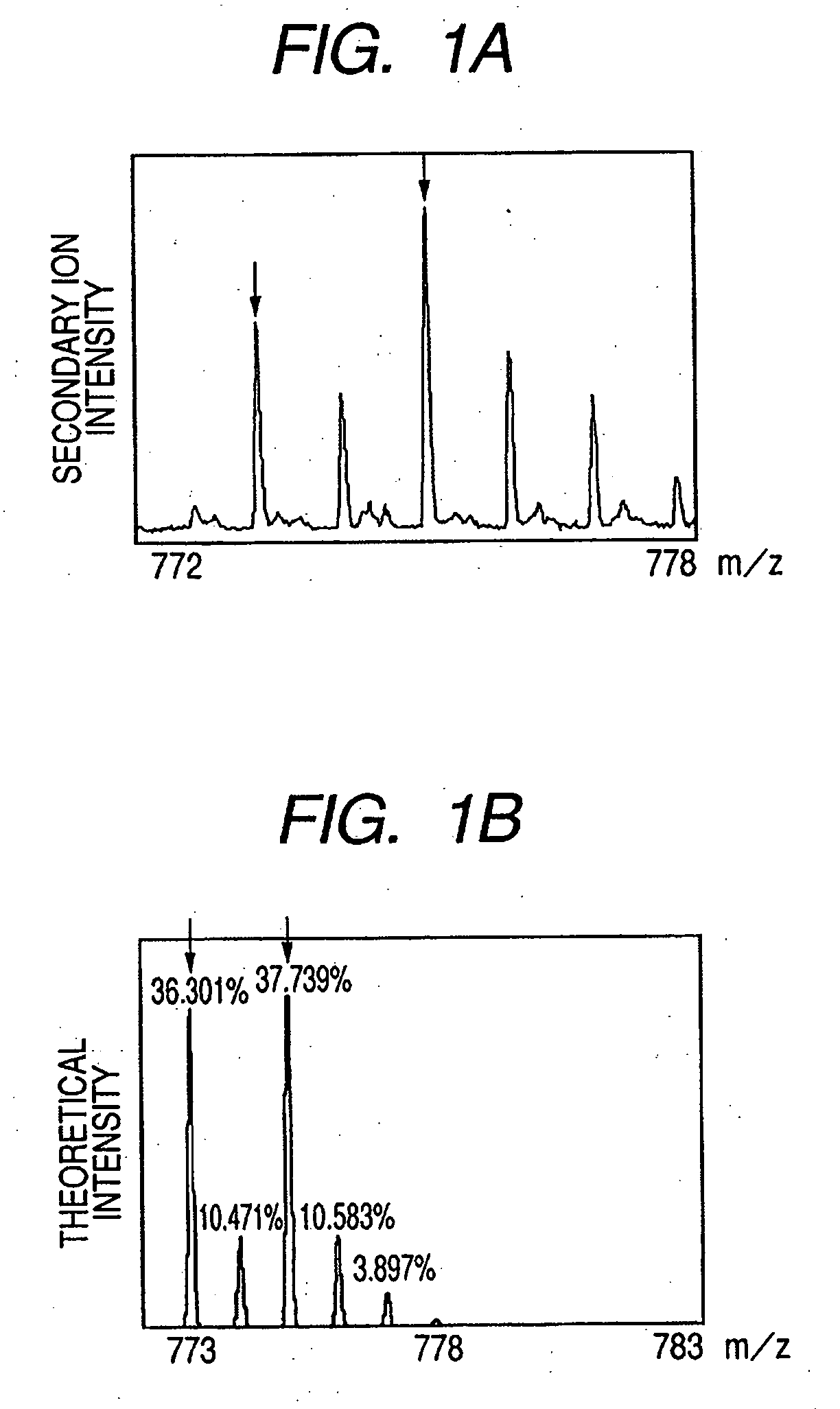
[0194] Upon measuring the positive and negative secondary ion mass spectra under the above conditions, in the positive secondary ion mass spectrum, secondary ions corresponding to the mass of the parent molecule of synthetic peptide I with added Au could be detected. It was possible to obtain an image generated by two-dimensional imaging that reflected the two-dimensional distribution state of the synthetic peptide I using these secondary ions that confo...
example 3
Silver Mirror Reaction Treatment for Chip Produced in Example 1
[0195] The chip produced in Example 1 was air-dried, and in a state where almost all moisture had evaporated, the chip underwent the following treatment (silver mirror reaction).
[0196] First, after preparing a silver nitrate solution, ammonia water was added thereto to form an ammonia complex of silver. An ammonia complex of silver was formed to prevent silver changing to silver oxide and separating out when the chemical solution became alkaline, and also to stabilize the oxidation-reduction potential value of silver.
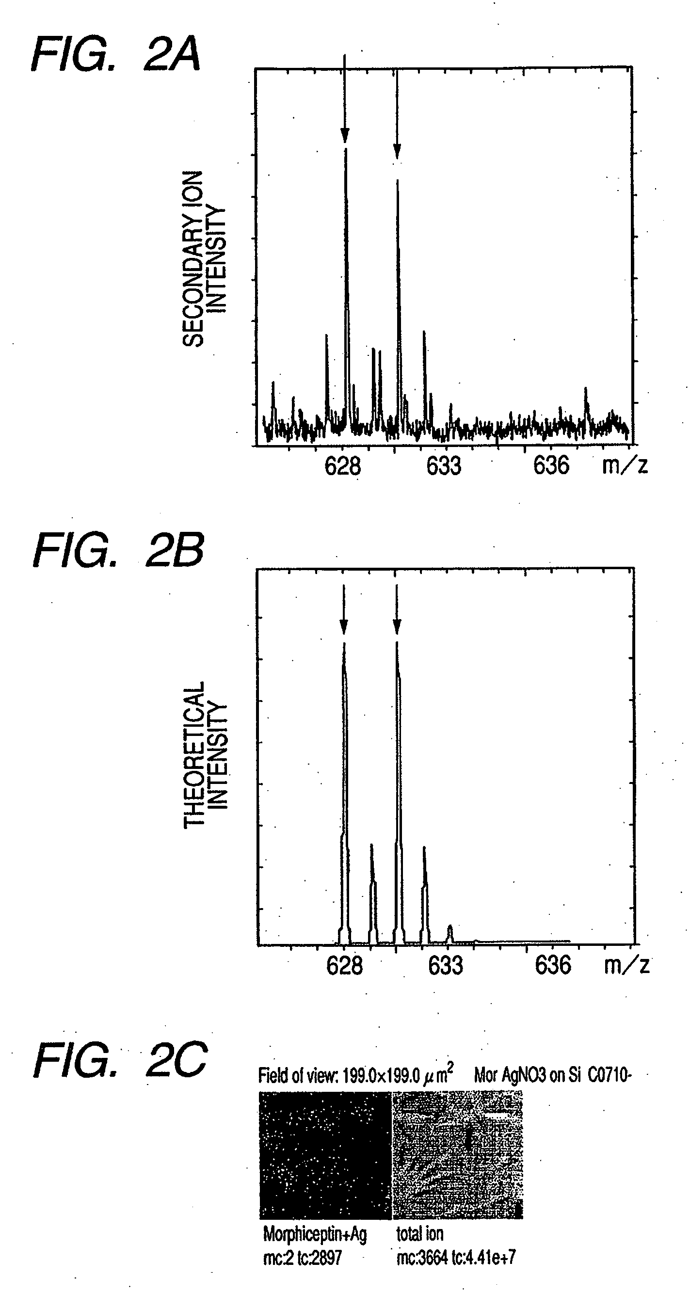
[0197] Next, an appropriate amount of an aqueous solution containing the silver ammonia complex was dropped onto the surface of the above substrate and left to stand for 10 min. Thereafter, a weak alkaline aqueous solution in which sodium hydroxide was added to a formaldehyde aqueous solution was dropped onto the surface of the above substrate in an appropriate amount. The substrate was allowed to stand ...
PUM
 Abstract
Description
Claims
Application Information
 - R&D
- Intellectual Property
- Life Sciences
- Materials
- Tech Scout
- Unparalleled Data Quality
- Higher Quality Content
- 60% Fewer Hallucinations
Browse by: Latest US Patents, China's latest patents, Technical Efficacy Thesaurus, Application Domain, Technology Topic, Popular Technical Reports.
© 2025 PatSnap. All rights reserved.Legal|Privacy policy|Modern Slavery Act Transparency Statement|Sitemap|About US| Contact US: help@patsnap.com