
Endoscopic devices and method of use

a technology of endoscopic devices and methods, applied in the field of endoscopic devices, can solve the problems of failure to achieve high ivf success rates and less than optimal solutions, and achieve the effect of minimizing the loss of embryos

Inactive Publication Date: 2006-08-17
FIDELITYCORP
View PDF57 Cites 26 Cited by
  • Summary
  • Abstract
  • Description
  • Claims
  • Application Information

AI Technical Summary

Benefits of technology

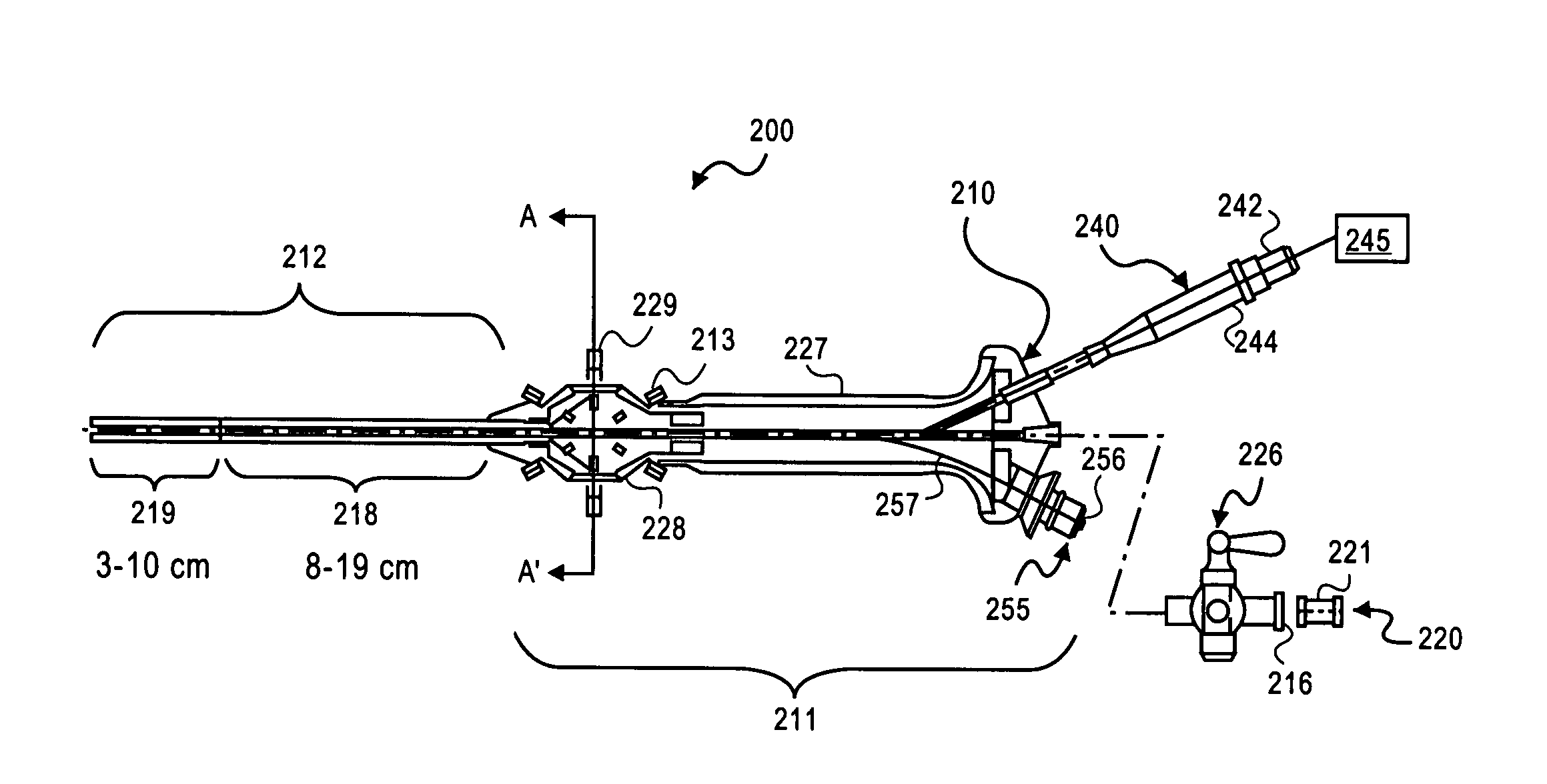
[0009] A catheter, an endoscope (hysteroscope), and a method of introducing at least one embryo into a uterus of a subject is described. One object of the device(s) and / or method is to provide a simple gentle method for intrauterine procedures such as embryo transfer and implantation. To accomplish this gentle transfer, an improved catheter (referred alternatively and interchangeably herein as “microcatheter”) with a beveled opening and tip is described. The catheter is able to work as both a microsurgical instrument, used in a method described herein to form an embryo-receiving pocket within the endometrial lining of a subject's uterus, and as the vehicle for transferring an embryo into the pocket. It has been observed that by gently securing an embryo within a pocket of endometrial lining, many of the risks of IVF, such as a tubal pregnancy, misplacement of the embryo, and loss of the embryo can be minimized. Tubal pregnancies, for example, are virtually eliminated according to this method.

Problems solved by technology

While the embryo transfer methods of these prior art types may be generally satisfactory for their intended purposes, implantation problems can arise in which the trauma to the delicate embryos by either an injection or “adhesion” may yield less than optimal solutions and fail to achieve high IVF success rates.

Method used


Image

  • Endoscopic devices and method of use
  • Endoscopic devices and method of use
  • Endoscopic devices and method of use

Examples


Embodiment Construction

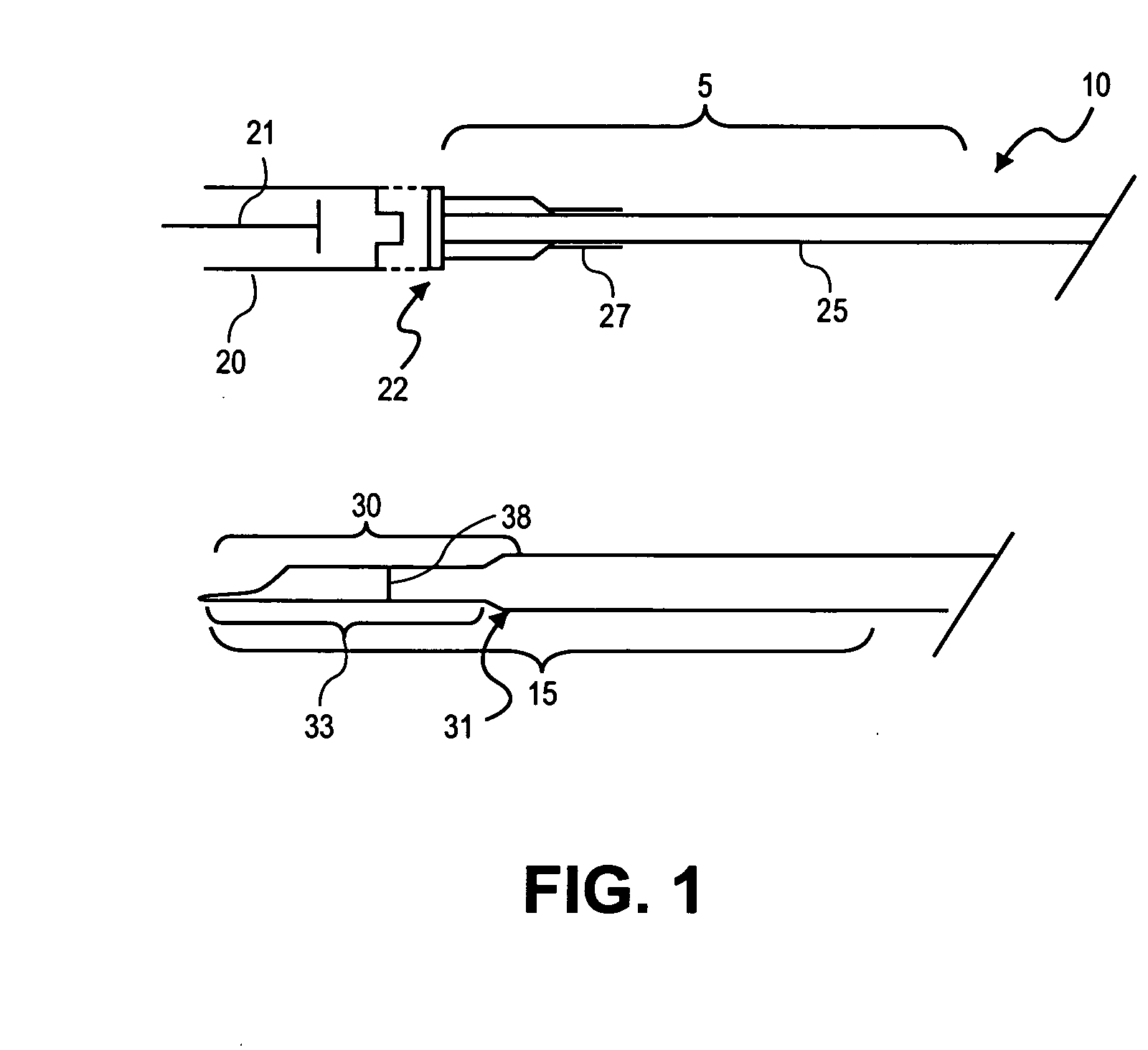
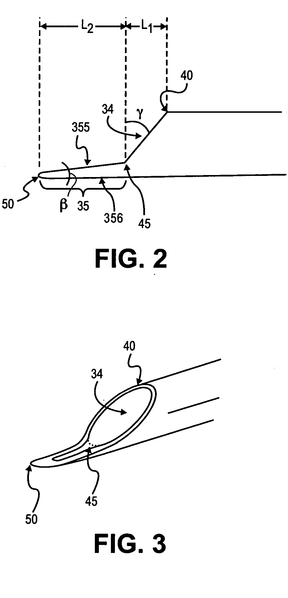
[0019] Referring now to the drawings, illustrated in FIGS. 1-3 is one embodiment of a microcatheter. Microcatheter 10 includes, in this embodiment, proximal portion 5 and distal 15. Microcatheter 10 includes shaft or cannula 25 having a lumen therethrough. Shaft 25 terminates at distal shaped end 30. Proximal portion 5 includes, at proximal end 22, a hub to mate with operational syringe 20, with plunger 21. The hub is, for example, a luer lock fitting. In one embodiment, extending approximately 25-30 millimeters from the hub is stabilizer 27 of, for example, a polymer tube having an inner diameter slightly greater than an external diameter of shaft 25.

[0020] Shaft 25 defines a lumen therethrough for, representatively, introducing one or more embryos into a uterus of a subject. In one embodiment, shaft 25 is an extruded one piece polymer material having a length on the order of 70 centimeters (cm). Suitable polymers for shaft 25 are selected such that the shaft has sufficient rigidi...


PUM


Abstract

A catheter including a shaft including a body with a proximal portion and a distal portion, the body defining an opening from the proximal portion to the distal portion, the distal portion having an exterior dimension suitable for insertion into a body of a subject as a procedural instrument, the distal portion having an end that is beveled in a first direction across an end opening, such that a length of the shaft to a first point is a first length and a length of the shaft to a second point on the end is a second length longer than the first length, a portion of the shaft extending from the second point defining a tip, wherein the tip comprises a material that has sufficient rigidity to penetrate an endometrial lining of a subject and sufficient flexibility to resist penetration of a uterine muscle of a subject.

Description

CROSS-REFERENCE TO RELATED APPLICATION [0001] This application is a continuation-in-part of co-pending U.S. patent application Ser. No. 10 / 725,623, filed Dec. 1, 2003 which is a continuation-in-part of co-pending U.S. patent application Ser. No. 10 / 080,177, filed Feb. 19, 2002, and which is a continuation-in-part of U.S. patent application Ser. No. 09 / 759,415, issued as U.S. Pat. No. 6,623,422 on Sep. 23, 2003.BACKGROUND [0002] 1. Field [0003] The embodiments disclosed herein relate generally to endoscopic devices, including hysteroscopes and related devices for microsurgical use. [0004] 2. Description of Related Art [0005] Improving the success of in vitro fertilization (IVF) depends on many factors, one of which is the delivery or transfer of the embryo to the endometrial lining of the uterus and the successful implantation of the embryo therein. It is well known in the art that assisting an embryo to adhere to, or implant within, a predetermined area of the endometrial lining of ...

Claims


Application Information

Patent Timeline
Patent Type & Authority Applications(United States)
IPC IPC(8): A61B1/00A61B1/04
CPCA61B1/303A61B17/435A61B2017/4216A61B2019/5206A61B2090/306
Inventor KAMRAVA, MICHAEL M.
Owner FIDELITYCORP
Learn More