Ultrasound diagnostic apparatus

a diagnostic apparatus and ultrasonic technology, applied in diagnostics, medical science, instruments, etc., can solve the problems of residual echo, line corresponding to the top beam being skipped, and the top line of each block on the doppler image is displayed unnaturally, so as to achieve greater power and wide bandwidth

Inactive Publication Date: 2006-08-17
ALOKA CO LTD
View PDF7 Cites 5 Cited by
  • Summary
  • Abstract
  • Description
  • Claims
  • Application Information

AI Technical Summary

Benefits of technology

[0017] Preferably, when a dummy receiving signal corresponding to the dummy transmitting beam is input, the Doppler image forming section discards the dummy receiving signal rather than using it for formation of the Doppler image.
[0018] Further preferably, the scanning control section controls the transmitting and receiving section such that a set of transmitting and receiving beams for formation of a luminance image is inserted at predetermined timing in each partial region which is designated. Also preferably, another dummy transmitting beams is formed after formation of the set of transmitting and receiving beams for formation of a luminance image and prior to formation of a set of transmitting and receiving beams for formation of a Doppler image. Specifically, from a viewpoint of unification of the receiving conditions, it is desirable to form a dummy transmitting beam after forming a set of transmitting and receiving beams for formation of a luminance image, and then form a set of transmitting and receiving beams for formation of a Doppler image. Here, generally, a transmitting signal for formation of a luminance image and a transmitting signal for formation of a Doppler image have different powers and different bandwidths. Specifically, the former has a wider bandwidth and a greater power than the latter.
[0019] In conventional ultras

Problems solved by technology

With the method shown in FIG. 7 of the above Reference 1, however, there are instances wherein the top line of each block on a Doppler image is displayed unnaturally.
In general, with regard to two beams which are successive in time, a transmission wave which has been transmitted when forming the preceding beam is also received in the receiving period regarding the following beam, resulting

Method used


Image

  • Ultrasound diagnostic apparatus
  • Ultrasound diagnostic apparatus
  • Ultrasound diagnostic apparatus

Examples


Embodiment Construction

[0027] Preferred embodiments of the present invention will be described in detail with reference to the accompanying drawings.

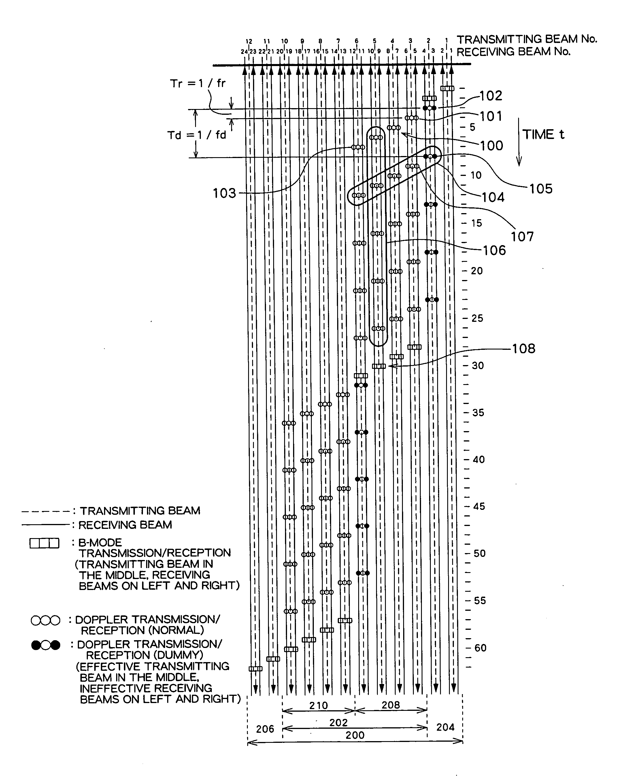
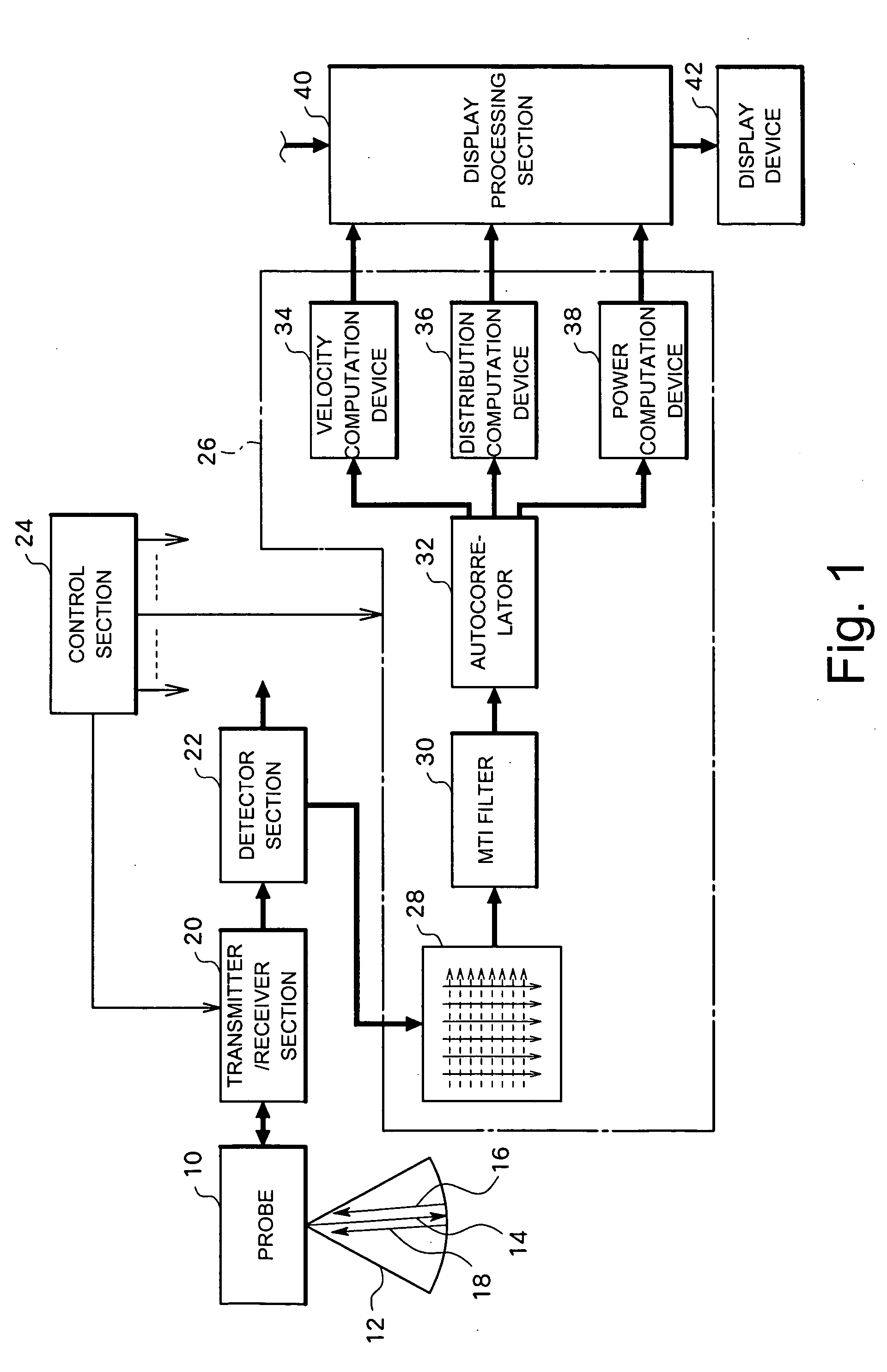
[0028]FIG. 1 shows an overall structure of an ultrasound diagnostic apparatus. This ultrasound diagnostic apparatus obtains Doppler information regarding blood flow within a living body and forms a two-dimensional image of the blood flow based on the Doppler information. It is also possible to form a tissue image representing a movement of a tissue such as a cardiac wall, in place of the image of blood flow. The transmission and reception sequence as will be described below is set in order to form an image of blood flow moving at a low velocity.

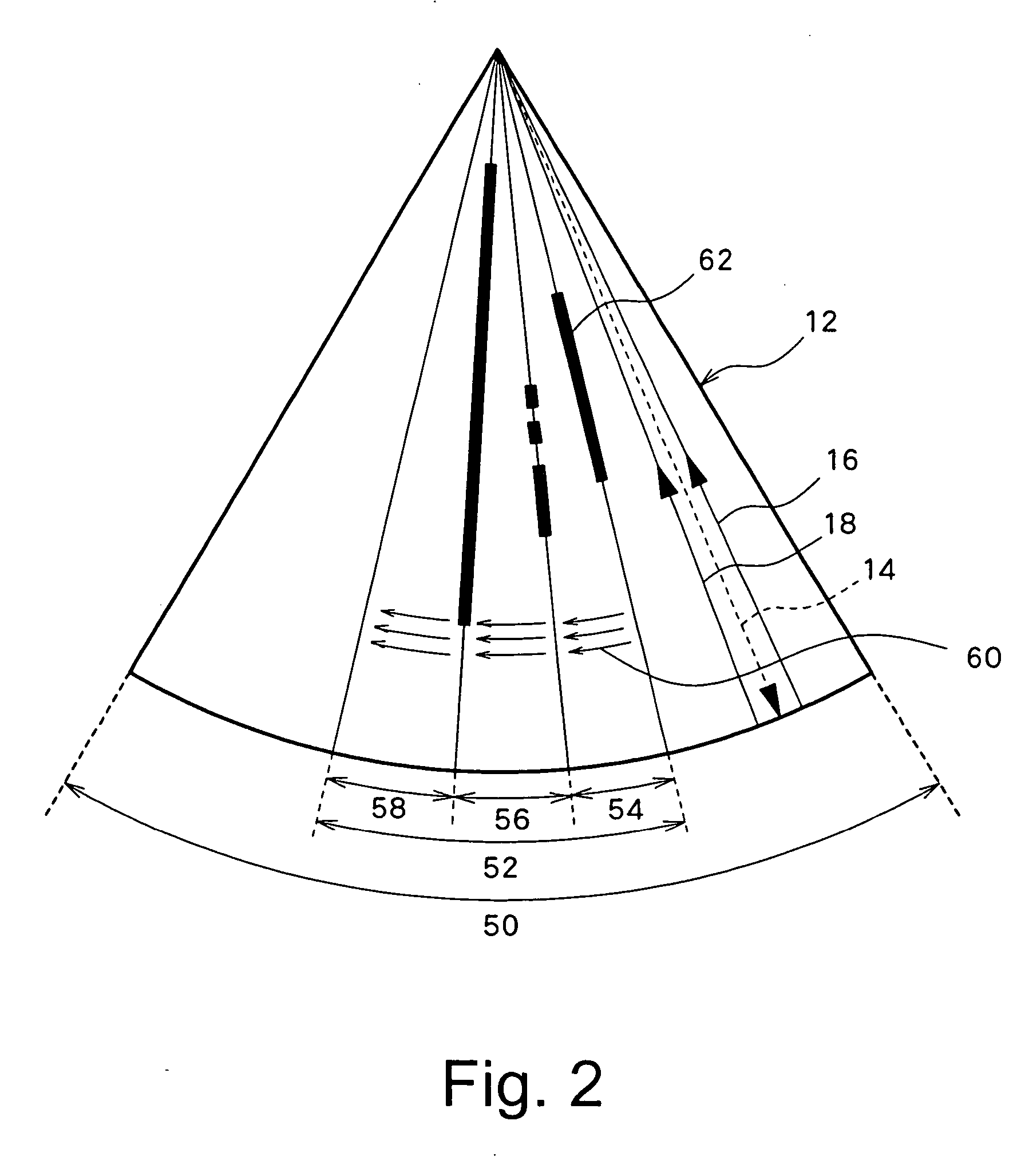
[0029] A probe 10 is brought into contact with a surface of a living body or is inserted into a body cavity of the living body. The probe 10 includes an array transducer (not shown) which is formed by a plurality of transducer elements. The array transducer generates ultrasound beams, which are electronically scanned...


PUM


Abstract

In an ultrasound diagnostic apparatus for forming a Doppler image, a plurality of partial regions are set within a scan region in which Doppler information is obtained. A partial scan operation is performed a plurality of times in a repetitive manner in each of the partial regions. In each partial region, a set of dummy transmitting and receiving beams is formed immediately before formation of the first set of transmitting and receiving beams. As the receiving beam in the first set of the transmitting and receiving beams is affected by the dummy transmitting beam, the receiving conditions can be unified over a plurality of sets of transmitting and receiving beams. A set of dummy transmitting and receiving beams may be provided immediately before the first partial scan operation or formation of a set of dummy transmitting and receiving beams in such a case may be omitted.

Description

BACKGROUND OF THE INVENTION [0001] 1. Field of the Invention [0002] The present invention relates to an ultrasound diagnostic apparatus, and more particularly to an ultrasound diagnostic apparatus for medical use, which performs transmission and reception of an ultrasound a plurality of times for each beam address for forming a Doppler image representing movement information of a moving object within a living body. [0003] 2. Description of Related Art [0004] When forming a two-dimensional Doppler image, an ultrasound diagnostic apparatus normally sequentially designates a beam address on a beam scan plane and performs transmission and reception of an ultrasound a plurality of times (eight to ten times, for example) for each beam address in a repetitive manner, thereby obtaining a plurality of (eight to ten, for example) receiving signals (beam data items) for each beam address. By performing a known autocorrelation operation for each depth within a living body based on these receivi...

Claims


Application Information

Patent Timeline
IPC IPC(8): A61B8/06
CPCG01S7/52085G01S7/52095G01S15/8979
Inventor OHSHIMA, NOBUOMOTOKAWA, KATSUFUMISEKI, YOSHINORI
Owner ALOKA CO LTD
Why Eureka
Try Eureka