Start time reduction device and electronic device

a technology of start time and reduction device, which is applied in the direction of program control, instruments, microcontrollers, etc., can solve the problems of increasing the boot time and longer the time for electronic devices to become usable, and achieve the effect of reducing the boot time and less time for electronic devices

Active Publication Date: 2006-08-17
PANASONIC CORP
View PDF14 Cites 47 Cited by
  • Summary
  • Abstract
  • Description
  • Claims
  • Application Information

AI Technical Summary

Benefits of technology

[0006] An object of the present invention is to provide a boot time reducing device that enables less time for an electronic apparatus to become usable after a boot instruction by user.

Problems solved by technology

This has resulted in a longer time for an electronic apparatus to become usable after a boot instruction by a user.
This necessitates time for expanding the compressed program during the boot time of a home appliance, which further increases the boot time.

Method used


Image

  • Start time reduction device and electronic device
  • Start time reduction device and electronic device
  • Start time reduction device and electronic device

Examples


first embodiment

[0070] First Embodiment

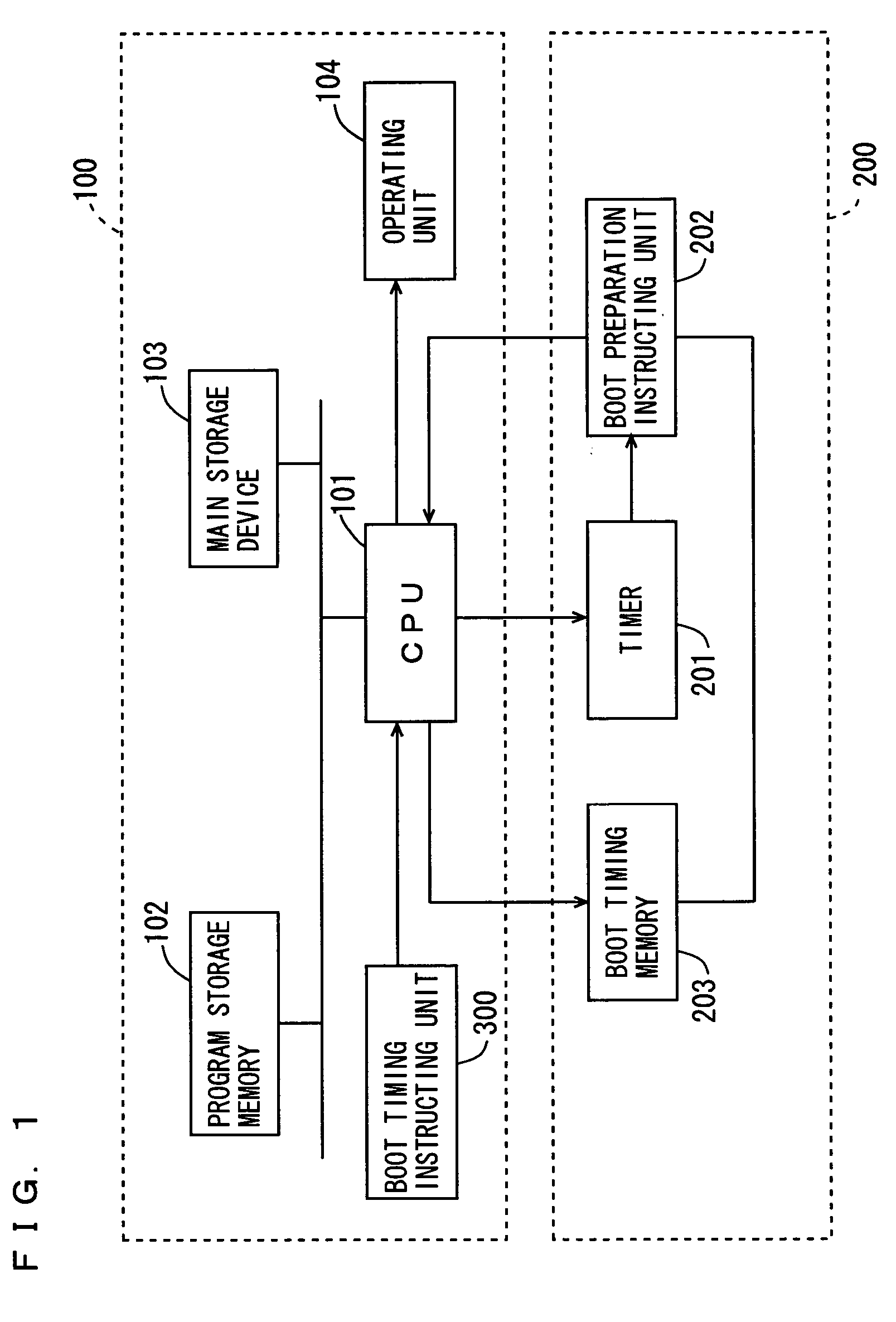
[0071]FIG. 1 is a block diagram showing the configuration of an electronic apparatus that includes a boot time reducing device according to a first embodiment of the invention.

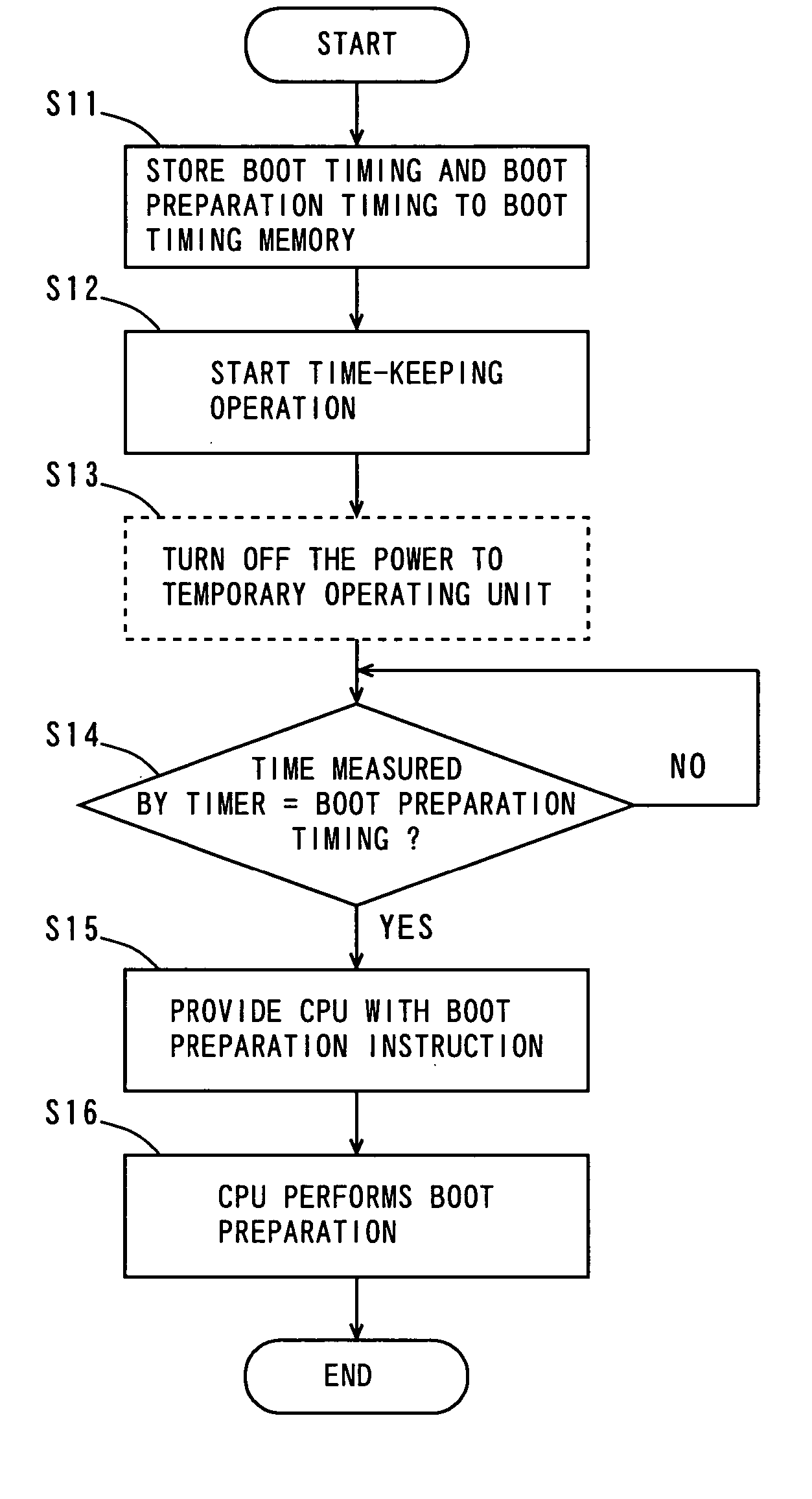
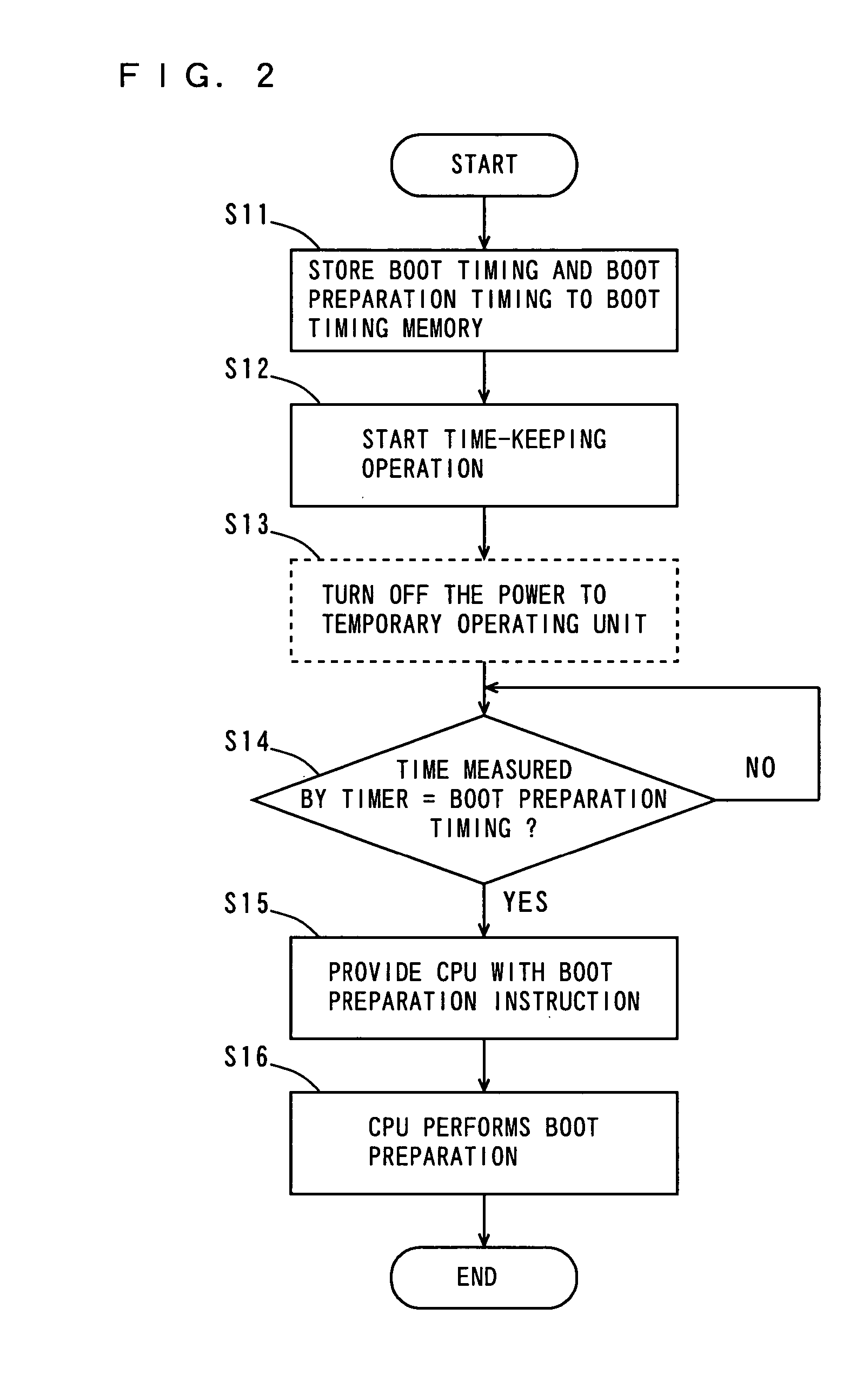
[0072] As shown in FIG. 1, the electronic apparatus includes a temporary (part-time) operating unit 100 and a normally (full-time) operating unit 200. The temporary operating unit 100, corresponding to a portion of the electronic apparatus that is not normally operating, starts operation in response to a boot instruction. Note that the boot instruction is generated when a user switches on the electronic apparatus or by user manipulation of a remote control or at a time preset by a timer. In this embodiment, the boot instruction is generated at a timer preset time.

[0073] The normally operating unit 200, corresponding to a portion of the electronic apparatus that is normally operating, provides the temporary operating unit 100 with a boot preparation instruction. A boot preparation will ...

second embodiment

[0093] Second Embodiment

[0094]FIG. 3 is a block diagram showing the configuration of an electronic apparatus that includes a boot time reducing device according to a second embodiment of the invention.

[0095] The electronic apparatus of FIG. 3 is different from the electronic apparatus of FIG. 1 as will now be described. The electronic apparatus of FIG. 3 is not provided with the boot timing instructing unit 300 of FIG. 1. Instead, the boot timing memory 203 stores a previous boot timing for the electronic apparatus. The CPU 101 predicts a boot preparation timing based on the previous boot timing stored in the boot timing memory 203, and stores the predicted boot preparation timing to the boot timing memory 203. More specifically, the CPU 101 decides as a boot preparation timing the timing earlier than the previous boot timing by an amount of time necessary for the boot preparation of the electronic apparatus.

[0096] In this embodiment, the CPU 101, timer 201, boot preparation instr...

third embodiment

[0126] Third Embodiment

[0127]FIG. 7 is a block diagram showing the configuration of an electronic apparatus that includes a boot time reducing device according to a third embodiment.

[0128] The electronic apparatus of FIG. 7 is different from the electronic apparatus of FIG. 3 as will now be described. The electronic apparatus of FIG. 7 has a remote control receiver 400 incorporated in the normally operating unit 200. A remote control 500 includes a boot preparation instructing unit 202 and a sensor 501.

[0129] The sensor 501 is composed of a pressure sensor that detects a pressure, a temperature sensor that detects a temperature, or a gyrosensor that detects an angular velocity, for example. The pressure sensor as the sensor 501 detects a pressure generated when the user holds the remote control 500, and outputs a signal indicative of the pressure to the boot preparation instructing unit 202. The temperature sensor as the sensor 501 detects a temperature of the remote control 500 t...


PUM


Abstract

With a temporary operating unit being operating, a user provides a boot timing using a boot timing instructing unit. This causes a CPU to compute a boot preparation timing based on the boot timing, and store the boot timing and boot preparation timing to a boot timing memory. At this time, a timer begins a time-keeping operation. After that, the user turns off the power to the temporary operating unit. A boot preparation instructing unit determines whether or not the time being measured by the timer coincides with the boot preparation timing stored in the boot timing memory. When the time measured by the timer coincides with the boot preparation timing stored in the boot timing memory, the boot preparation instructing unit provides the CPU with a boot preparation instruction. This turns on the power to the temporary operating unit, and the CPU performs a boot preparation.

Description

TECHNICAL FIELD [0001] The present invention relates to a boot time reducing device that reduces the time for an electronic apparatus to become usable after a boot instruction, and an electronic apparatus including the boot time reducing device. BACKGROUND ART [0002] With the recently increased diversity and networking in home appliances, programs for controlling home appliances have rapidly enlarged in scale. This has resulted in a longer time for an electronic apparatus to become usable after a boot instruction by a user. [0003] A large-scaled program is typically compressed in order to reduce the capacity needed in a memory that stores the program. This necessitates time for expanding the compressed program during the boot time of a home appliance, which further increases the boot time. [0004] A technique is suggested in which an image formation system comprising a master device and a slave device predicts the warm-up time of the slave device (refer to JP 2001-7961). In this imag...

Claims


Application Information

Patent Timeline
Patent Type & Authority Applications(United States)
IPC IPC(8): G06F15/177G06F1/00G06F9/06G06F9/445
CPCG06F9/4403G06F1/00G06F9/06
Inventor YAMADA, MIKIHIKOMIZOBATA, NORIHIKOARAKAWA, TAKU
Owner PANASONIC CORP
Why Eureka
Try Eureka