Thermosyphon device, cooling and heating device and method using the thermosyphone device, and plant cultivating method

a technology of thermosyphon and wick, which is applied in the direction of indirect heat exchangers, lighting and heating apparatus, and stationary conduit assemblies, etc., can solve the problems of difficult to maintain a state in which these wicks are difficult to be easily produced, and the major construction work must be performed for a change in the tube arrangement, etc., to achieve the effect of simple structure, low cost and easy production

Inactive Publication Date: 2006-08-24
TAKEHARA CHIKARA
View PDF10 Cites 21 Cited by
  • Summary
  • Abstract
  • Description
  • Claims
  • Application Information

AI Technical Summary

Benefits of technology

[0012] According to the thermosyphon device of the present invention, in the double tube type thermosyphon device in which the inner tube is disposed to be longitudinally passed through the outer tube disposed to be horizontally long, in which the working space defined between the outer tube and the inner tube is provided with the operating liquid and is hermetically closed, and in which heat exchange is performed between the outside and the inside of the outer tube while allowing the thermal source fluid to flow through the inner tube, the large number of circumferentially-formed narrow concave grooves are formed both in the inner wall surface of the outer tube facing the working space and in the outer wall surface of the inner tube facing the working space; and the operating liquid is raised in the circumferential direction of the wall surface by capillary attraction via the narrow concave grooves, and is evaporated on the evaporating portion of either of the inner wall surface of the outer tube and the outer wall surface of the inner tube, whereas the operating liquid is condensed on the other wall surface, so that the outside of the outer tube is cooled or heated. Therefore, the thermosyphon device of the present invention can be easily produced by an extremely simple structure without using a mesh wick, or the like, that is expensive and has difficulty in being attached. Although the thermosyphon device of the present invention is produced at low cost, the surroundings of the device can be cooled and heated by an efficient heat transfer. Additionally, the operation to cool or heat the surroundings can be freely selected and performed merely by changing the thermal source fluid to be supplied to the inner tube.
[0013] Additionally, since the narrow concave groove has the groove width Wg as an allowable maximum groove width, and has the predetermined groove depth, a horizontally-mounted double tube type thermosyphon that does not require the work of closely attaching a mesh wick onto the inside of the tube and that has a simple structure formed at low cost can be put to practical use.
[0014] Additionally, since the thermosyphon device is of an eccentric double tube type in which the inner tube has the axial center located at a position deviated from the axial center of the outer tube and in which the axial center of the inner tube is located below the axial center of the outer tube, the operating liquid is efficiently evaporated from the narrow concave grooves formed in the outer wall surface of the inner tube, and is condensed on the entire outer wall surface including the grooves and parts other than the grooves at a condensing step, and hence excellent heat transportation efficiency can be obtained.
[0015] Additionally, since the cooling and heating device is structured that uses the thermosyphon device of claim 1 or claim 2 and that performs switching between a cold fluid and a hot fluid serving as thermal source fluids so as to cool and heat the surroundings of the device as a single device, the cooling and heating device can be effectively used while freely performing switching between cooling and heating by installing the device in various locations required to cool and heat the surroundings.
[0016] Additionally, according to the present invention, in the double tube type thermosyphon device in which the inner tube is disposed to be longitudinally passed through the outer tube disposed to be horizontally long, in which the working space defined between the outer tube and the inner tube is provided with the operating liquid and is hermetically closed, and in which heat exchange is performed between the outside and the inside of the outer tube while allowing the thermal source fluid to flow through the inner tube, the large number of circumferentially-formed narrow concave grooves are formed either in the inner wall surface of the outer tube facing the working space or in the outer wall surface of the inner tube facing the working space; and the operating liquid is raised in a circumferential direction of the wall surface by capillary attraction via the narrow concave grooves, and is evaporated on the evaporating portion of either of the inner wall surface of the outer tube and the outer wall surface of the inner tube, whereas the operating liquid is condensed on the other wall surface, so that the outside of the outer tube is cooled or heated. Therefore, the surroundings can be effectively cooled and heated when necessary, even in the double tube type thermosyphon in which the narrow concave grooves are formed either in the inner wall surface of the outer tube or in the outer wall surface of the inner tube.
[0017] Additionally, according to the present invention, in the cooling and heating method using the double tube type thermosyphon in which the inner tube is disposed to be longitudinally passed through the outer tube disposed to be horizontally long, in which the working space defined between the outer tube and the inner tube is provided with the operating liquid and is hermetically closed, and in which heat exchange is performed between the outside and the inside of the outer tube while allowing the thermal source fluid to flow through the inner tube, the large number of circumferentially-formed narrow concave grooves are formed both in the inner wall surface of the outer tube facing the working space and in the outer wall surface of the inner tube facing the working space; the operating liquid is always borne on the tube surfaces by capillary attraction via the narrow concave grooves; and the outside of the outer tube is cooled or heated in accordance with the thermal source fluid while guiding the operating liquid upwardly and downwardly on the surface of each tube. Therefore, the surroundings of the device can be cooled and heated with a simple structure at the level of practical use without using a mesh wick that is expensive and has difficulty in being attached. Additionally, the operation to cool or heat the surroundings can be freely selected and performed merely by changing the thermal source fluid to be supplied to the inner tube.

Problems solved by technology

When switching between cooling and heating is performed after the device is installed, there has been a fear that major construction work must be performed for a change in the tube arrangement.
However, it is difficult to maintain a state in which these wicks are in close contact with the tube walls.
Thus, there has been a problem in the fact that production and adjustment in installation cannot be easily performed or in the fact that high cost is entailed because the tubes must be made of the same material as a container in connection with electrolytic corrosion.
Additionally, because of thermal resistance caused by the structure of the porous wick or by insufficient adhesion of the wick to the tube wall, an effect desired enough to be put to practical use can be hardly achieved especially when the area around the outer tube having a high temperature is cooled.

Method used


Image

  • Thermosyphon device, cooling and heating device and method using the thermosyphone device, and plant cultivating method
  • Thermosyphon device, cooling and heating device and method using the thermosyphone device, and plant cultivating method
  • Thermosyphon device, cooling and heating device and method using the thermosyphone device, and plant cultivating method

Examples


examples 1 and 2

Design Examples 1 and 2

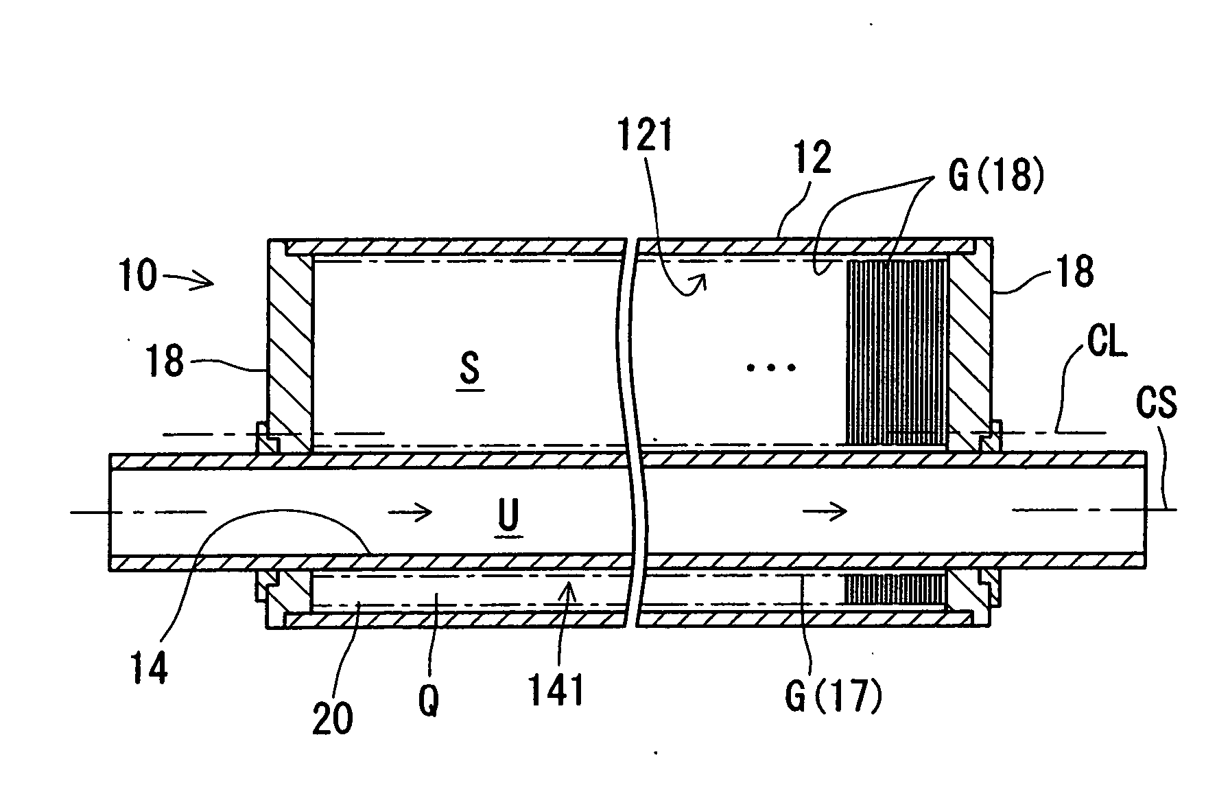
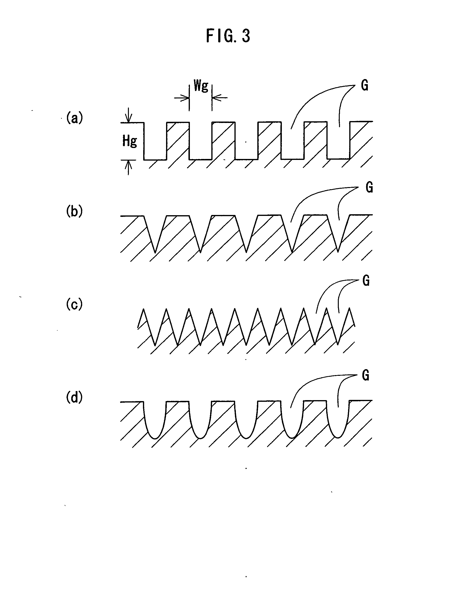
[0055] When the surroundings of the device are cooled at the maximum heat transportation amount during cooling (cold water is used as a fluid flowing through the inner tube), the outer tube serves as an evaporating portion, and the inner tube serves as a condensing portion. Therefore, it is recommended to calculate the maximum heat transportation amount by the capillary pressure limit of the outer tube group as the maximum heat absorption amount. Accordingly, calculated values Qmax / L (W / m) of the maximum heat transfer amount per unit length during cooling when ethanol and water are each used as an operating fluid are shown in Table 1 concerning Design Example 1 and Table 2 concerning Design Example 2. In the calculation, the operating temperature (steam temperature) Tv was 10° C. In the tables, Qmax / L(W / m) is the maximum heat transfer amount per unit length, Wg is the width of the outer tube grooves (narrow concave grooves), Hmax is the maximum capillary heigh...

examples 3 and 4

Design Examples 3 and 4

[0057] When the surroundings of the device are heated at the maximum heat transportation amount during heating (warm water is used as a fluid flowing through the inner tube), the outer tube serves as a condensing portion, and the inner tube serves as an evaporating portion. Therefore, it is recommended to calculate the maximum heat transportation amount by the capillary pressure limit of the inner tube grooves as the maximum heat radiation amount. Accordingly, calculated values Qmax / L(W / m) of the maximum heat transfer amount per unit length during heating when ethanol and water are each used as an operating fluid are shown in Table 3 and Table 4. In the calculation, the operating temperature (steam temperature) Tv was 40° C.

TABLE 3Table 3 Maximum heat transfer amount of inner tube grooves duringheating (operating fluid: ethanol)WgHmaxSgHg [mm]Ng[mm][mm][mm]0.20.30.4[number / m]0.413.40.5—15550011111.0—1003217141.5—732375262.0—581874170.317.90.5101623144912501....


PUM


Abstract

A thermosyphon device is provided for both cooling and warming (heating) enabling, by a simple structure, the easy installation operation, elimination of the need of adjusting operation, a reduction in manufacturing cost, and an increase in heat transportation efficiency. A large number of circumferentially-formed narrow concave grooves (G) are formed in the inner wall surface (121) of an outer tube (12) and in the outer wall surface (141) of an inner tube (14) facing the working space (S) of a double tube type thermosyphon disposed in the lateral direction. An operating liquid (Q) is evaporated at the evaporating portion of either of the inner wall surface (121) of the outer tube and the outer wall surface (141) of the inner tube and is condensed on the other wall surface while being raised in the circumferential direction of the wall surfaces (121, 141) by a capillary attraction via the narrow recessed grooves (G) to cool or heat the outer area of the outer tube. Depending on whether the surroundings of the outer tube are cooled or heated, a thermal source fluid of refrigerant or heat medium is supplied into the inner tube.

Description

TECHNICAL FIELD [0001] This invention relates to a thermosyphon. More particularly, this invention relates to a double tube type thermosyphon device that is used by passing an inner tube, through which a thermal source fluid flows, through an outer tube and that is multifunctional to be usable either for cooling or for heating, relates to a cooling and heating device using the thermosyphon device, relates to a cooling and heating method using the thermosyphon device, and relates to a plant cultivating method using the thermosyphon device. BACKGROUND ART [0002] Although a thermal converter, such as a heat pump, in which heat exchange efficiency falls in proportion to the smallness of a temperature difference between heat exchange fluids is known, a thermosyphon has recently come into practical use. The thermosyphon is capable of conveying a large amount of heat in a state of keeping the temperature difference therebetween small while utilizing an evaporation or condensation phase cha...

Claims


Application Information

Patent Timeline
Patent Type & Authority Applications(United States)
IPC IPC(8): F24J3/08F28D15/00F28D15/02
CPCF28D1/0226F28D15/0233F28D15/046
Inventor TAKEHARA, TOSHIOKASI, HIROAKI
Owner TAKEHARA CHIKARA
Why Eureka
Try Eureka