Contactor for electronic parts and a contact method

a technology of electronic parts and contacts, applied in the field of contacts for electronic parts, can solve the problems of increasing electric power consumption, difficult to bring all terminals of an electronic part into contact with corresponding contacts, and difficulty in obtaining good contacts

Inactive Publication Date: 2006-08-24
SOCIONEXT INC
View PDF3 Cites 30 Cited by
  • Summary
  • Abstract
  • Description
  • Claims
  • Application Information

AI Technical Summary

Benefits of technology

[0035] It is a general object of the present invention to provide an improved and useful cont...

Problems solved by technology

Thus, an attempt has been made to improve a processing speed by high-integration of internal circuits, which causes an increase in electric power consumption.
Thereby, it has become difficult to bring all terminals of an IC into contact with corresponding contact pieces of a contactor with an appropriate positional relationship.
That is, if an attempt is made to arrange the contact pieces of the contactor at positions corresponding to the electrode terminals of the IC, each of the electrode terminals of the IC cannot agree with the corresponding one of the contact pieces since there is a positional error in the positions of the contact pieces and the there also is a positional error in the electrode terminals of the IC.
Accordingly, it is difficult to obtain a good contact and there it may be difficult to perform a desired electric test.
Specifically, a large part of the electrode terminals contacts with contact portions of the corresponding contact pieces with low contact resistances, while a part of the electrode terminals is brought into contact with the contact portions of the contact pieces at positions off from the center thereof due to the positional errors of the electrode terminals of the IC and the contact pieces of the contactor, which causes a problem in that the contact is made in a state where only a low contact resistance is achieved.
Although the required position accuracy can be relaxed by increasing an area of the contact portions of the contactor, it is not practical to increase the area of the contact portions since further reduction has been progressed in the pitch of the electrode terminals of the ...

Method used


Image

  • Contactor for electronic parts and a contact method
  • Contactor for electronic parts and a contact method
  • Contactor for electronic parts and a contact method

Examples


first embodiment

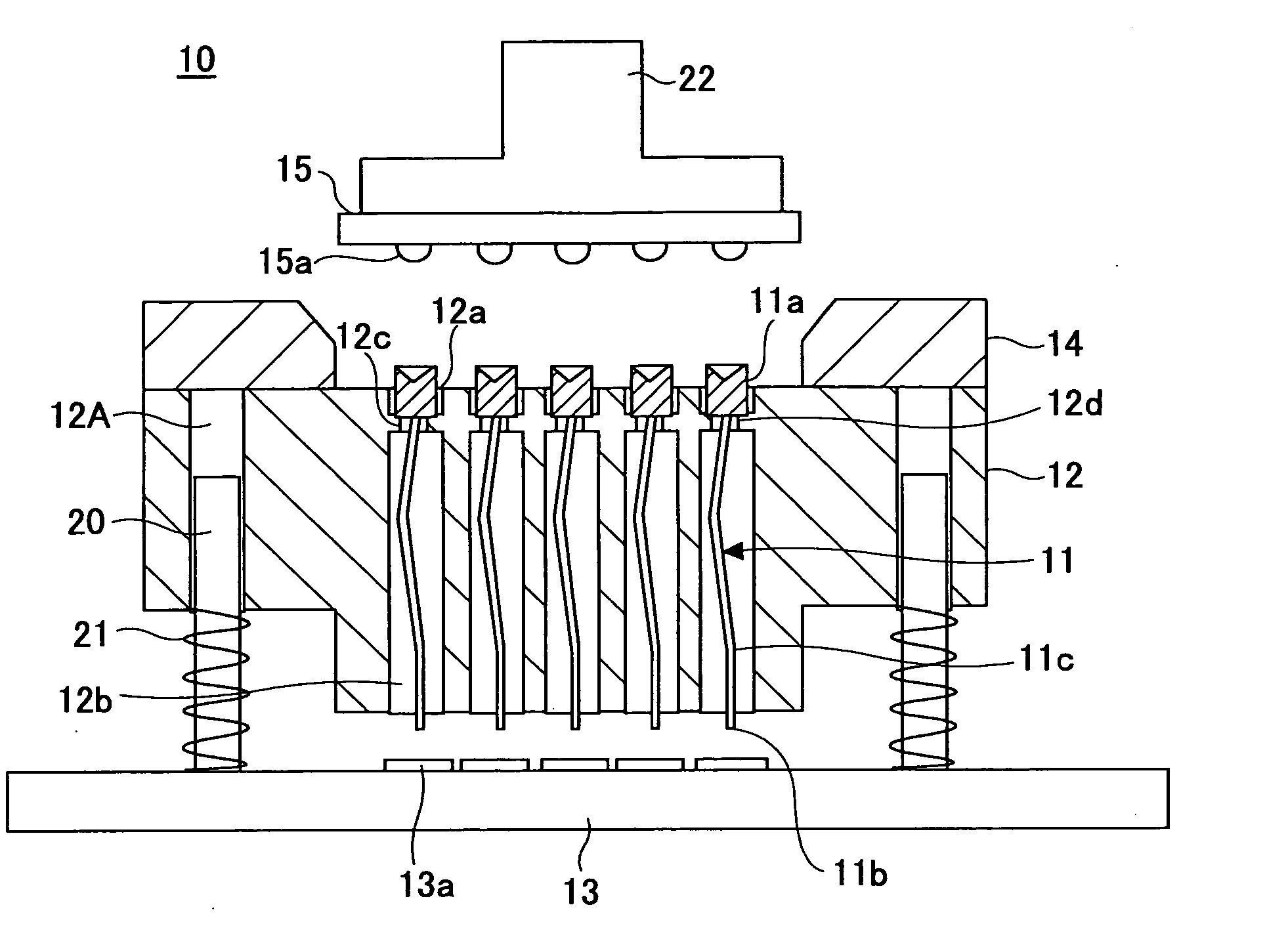
[0093] The contactor 10 according to the present invention comprises a plurality of contact pieces 11 that are brought into contact with external connection electrode terminals of a semiconductor integrated circuit device (hereinafter, referred to as IC) as an electronic part. The contact pieces 11 are arranged in a base 12, and a cover is provided in an upper portion of the base 12.

[0094] An opening into which an IC 15 as an electronic part (refer to FIG. 6) is inserted is formed in the cover 14. The IC 15 is accommodated in the opening of the cover 14 with a surface where electrode terminals 15a are formed facing downward. The electrode terminals 15a are brought into contact with the contact pieces 11 by pressing the IC 15 via the cover 14 so as to achieve an electric contact.

[0095] The base 12 is preferably formed of a plastic material, and, for example, liquid crystal polymer (LCP), polyamide resin or polyether ether ketone (PEEK) may be used. A for the substrate 13, an insulat...

second embodiment

[0117] The contactor 30 is not provided with contact portion holes 12a in the base 12, as shown in FIG. 12 and FIG. 13, and, instead, a guide plate 32 is provided above the base 12. The guide plate 32 is positioned between the base 12 and cover 14, and is movable in a transverse direction.

[0118] Contact portion holes 32a are provided in the guide plate 32 in accordance with the contact pin holes 12b provided in the base 12. Thus, the contact portion holes 32a are provided in accordance with the contact portions 11a of the contact pieces 11.

[0119] In the contactor according the above-mentioned first embodiment, each contact portion hole 12a is larger than each contact portion 11a, and when the first contact portions 11a are at arbitrary positions in the contact portion holes 12a, the positions of the electrode terminals 15a and the positions of the first contact portions 11a of the contact pieces 11 fluctuate largely in an initial state of contact. If an amount of offset in the pos...

third embodiment

[0124] A description will be given, with reference to FIG. 16, of a contactor according to the present invention.

[0125] The contactor 40 according to the third embodiment has an actuator 42, which gives a vibration to the base 12. The actuator 42 is constituted by, for example, an ultrasonic vibrator or a mechanical vibrator. The actuator 42 is operated for a period from a time when the electrode terminals 15a of the IC 15 to be tested begun to make a contact with the first contact portions 11a of the contact pieces 11 and until a final contact state is established so as to give a vibration to the base 12.

[0126] According to the base being vibrated, the first contact portions 11a are also vibrated. Thereby, coefficient of friction between the first contact portions 11a and the base 12 is reduced apparently, and the first contact portions 11a have become easily movable. That is, by giving a vibration to the base 12, it becomes possible to easily perform the positioning according to ...


PUM


Abstract

A contactor for electronic parts can provide an appropriate and uniform contact with respect to a plurality of electrode terminals in an electronic part such as an IC. Each of a plurality of contact members has a first contact portion on one end thereof and a second contact portion on the other end thereof, the first contract portion having a recessed portion that receives one of the electrode terminals of the electronic part. A base accommodates and supports the plurality of the contact members. The first contact portion is movable in a horizontal direction.

Description

BACKGROUND OF THE INVENTION [0001] 1. Field of the Invention [0002] The present invention relates to contactors for electronic parts and, more particularly, to a contactor for electronic parts that is used for a characteristic test of electronic parts such as a semiconductor integrated circuit device and a contact method using such a contactor. [0003] 2. Description of the Related Art [0004] In recent years, miniaturization, reduction in thickness and reduction in weight of portable electronic equipments (telephones, cameras, personal computers, etc.) have been advanced, and improvement in performance, miniaturization and high-integration have also been advanced with respect to semiconductor integrated circuit devices (hereinafter, referred to as ICs) that constitute electronic circuits of such portable electronic equipments. In many cases, as a form of an IC package, a ball-grid array (BGA) type is used, which has a small pitch of terminals so as to save a space. [0005] Moreover, i...

Claims


Application Information

Patent Timeline
IPC IPC(8): G01R31/02
CPCG01R1/0466G01R1/0483A01K69/10A01K75/00
Inventor KOHASHI, NAOHITOMARUYAMA, SHIGEYUKIARISAKA, YOSHIKAZUMUROTANI, HIROYUKIONO, KATSUHIKO
Owner SOCIONEXT INC
Why Eureka
Try Eureka