Radio frequency integrated circuit having a physical layer portion integrated therein

a radio frequency integrated circuit and physical layer technology, applied in the direction of transmission, data switching by path configuration, electrical equipment, etc., can solve the problems of inability to save power in non-beacon mode, delay in transmission downstream communication, and suffer from above-described conventional radio frequency lsi, etc., to achieve the effect of reducing mac layer burden, reducing transmission time, and reducing transmission tim

Inactive Publication Date: 2006-08-24
LAPIS SEMICON CO LTD
View PDF4 Cites 52 Cited by
  • Summary
  • Abstract
  • Description
  • Claims
  • Application Information

AI Technical Summary

Benefits of technology

[0025] According to an aspect of the present invention, at the time point at which the data necessary for determining the received data transfer mode are fixed in the physical layer portion, the physical layer portion latches the data and notifies the MAC layer, so that, during receiving subsequent data, the network layer can transfer the data and the MAC layer can determine the transfer mode. This can provide more time for the transmission of information for the transfer mode determination to the MAC layer and for the transfer mode determination by the MAC layer, thereby allowing more requirements from users to be satisfied.
[0026] According to another aspect of the invention, the radio frequency LSI comprises the MAC layer, so that the radio f

Problems solved by technology

The non-beacon mode thus cannot save power with the intermittent operation unlike the beacon mode.
In this method, the end devices periodically send out requests to the base station before receiving the downstream data, thereby causing a transmission delay in the downstream communication.
The above-described conventional radio frequency LSI, however, suffers from the following pr

Method used


Image

  • Radio frequency integrated circuit having a physical layer portion integrated therein
  • Radio frequency integrated circuit having a physical layer portion integrated therein
  • Radio frequency integrated circuit having a physical layer portion integrated therein

Examples


Embodiment Construction

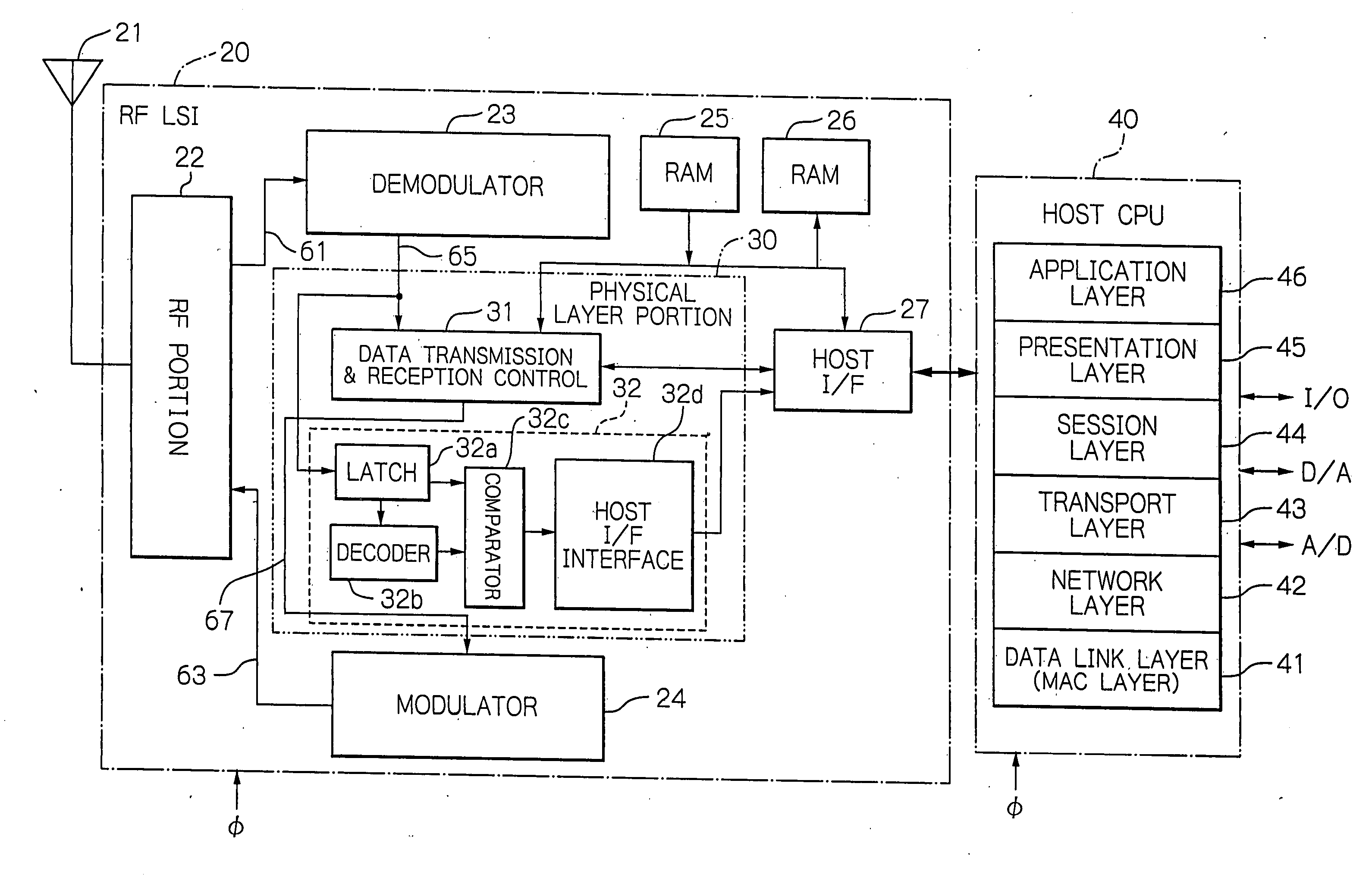
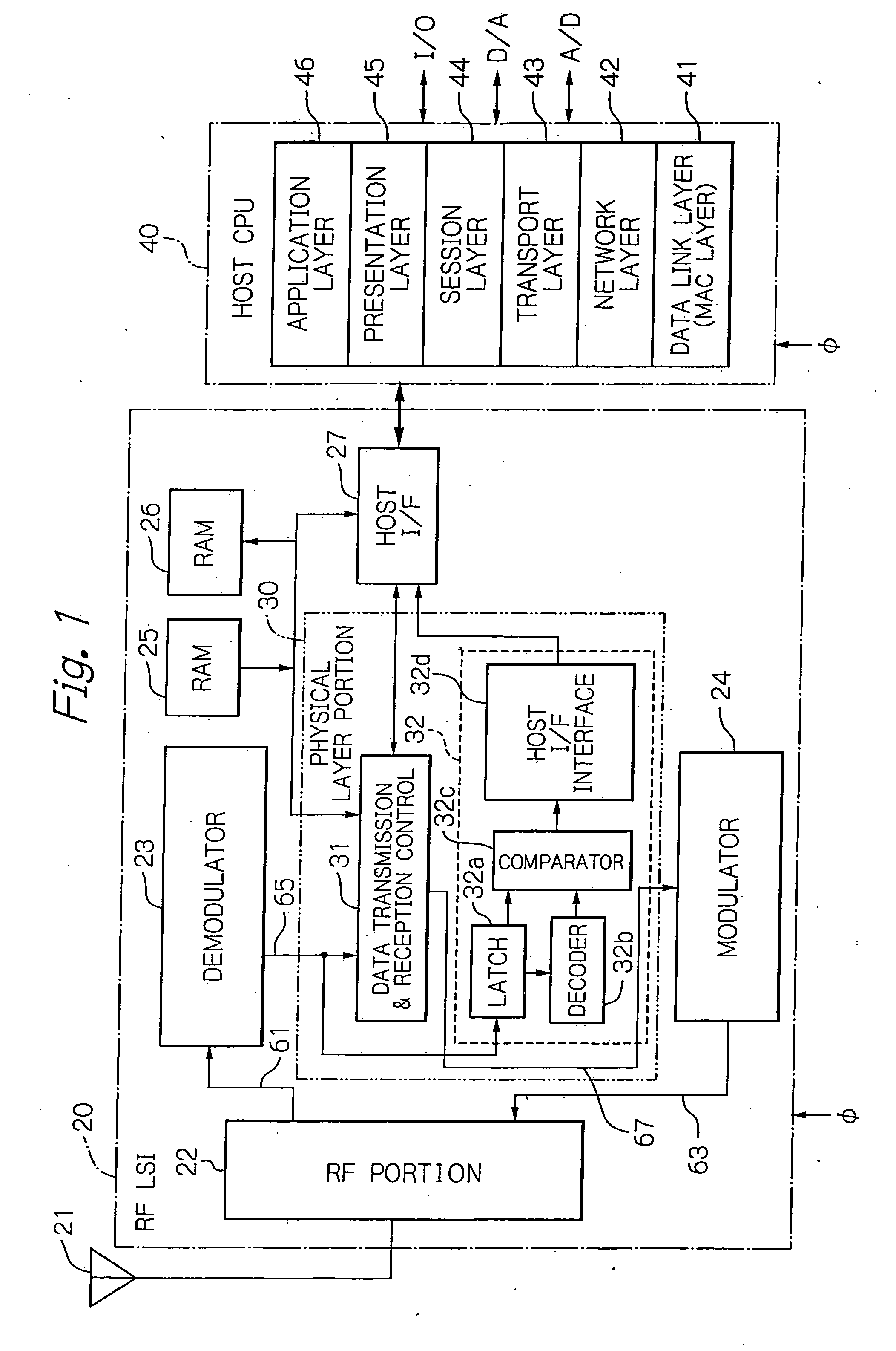
[0039] At first, reference will be made to FIG. 7 showing a communication layer model of a protocol configuration of ZigBee for use in the short-range radio frequency communication, and to FIG. 8 showing a network model of ZigBee. The protocol configuration of ZigBee includes, for example, a physical layer 1 and a data link layer 2 under the international standard IEEE 802.15.4 for WL-PAN (Wireless Personal Area Network). Thereover, a network layer 3, a transport layer 4, a session layer 5, a presentation layer 6, and an application layer 7 are positioned in this order from the lower.

[0040] The ZigBee network in the network layer 3 has a cluster tree structure which integrates the star type topology with the mesh type topology under IEEE 802.15.4. In the model of a ZigBee network shown in FIG. 8, there is a single ZigBee coordinator 11. ZigBee routers 12 form a mesh type of network, as depicted with fat arrows 14. The ZigBee routers 12 have ZigBee end devices 13 interconnected to f...


PUM


Abstract

A ZigBee-compliant radio frequency LSI includes a physical layer portion and a modulator. The physical layer portion has an RF portion, a demodulator, a data transmission and reception control, and a transfer mode determination portion. The transmission and reception control converts, during reception, symbol data received by the demodulator into the byte data received, and outputs, during transmission, the symbol data to be transmitted to the modulator. The determination portion determines, when the first identification data in the received data from the RF portion necessary for determining the received data transfer mode are fixed, the data length of the subsequent second identification data. The determination portion latches, when data corresponding to the determined length of the second identification data are fixed, the data necessary for determining the received data transfer mode to transfer the data to the MAC layer.

Description

BACKGROUND OF THE INVENTION [0001] 1. Field of the Invention [0002] The present invention relates to a radio frequency integrated circuit, and more specifically to a radio frequency large-scale integrated circuit (LSI) which has its physical-layer interface compliant with IEEE (Institute of Electrical and Electronics Engineers) 802.15.4 and which is based upon ZigBee (trademark of ZigBee Alliance) technology. The invention more particularly relates to the control of receiving data in the radio frequency integrated circuit. [0003] 2. Description of the Background Art [0004] ZigBee is one of the short-range radio frequency communication standards and classified into the radio frequency communication standard which uses sixteen channels into which divided is the same frequency bandwidth of 24 GHz as the wireless local area network (LAN) standard, IEEE 802.11b. [0005] Conventional radio frequency integrated circuits, sometimes simply referred to as “radio frequency LSIs”, using ZigBee t...

Claims


Application Information

Patent Timeline
IPC IPC(8): H01P1/00H01P5/00
CPCH04B1/40H04L12/28
Inventor SATOU, SHIGEYUKI
Owner LAPIS SEMICON CO LTD
Why Eureka
Try Eureka