Automobile tire monitoring system and tire identification method

a technology for monitoring systems and tires, applied in vehicle tyre testing, roads, instruments, etc., can solve problems such as incorrect information about pressure and temperature as correlated with tires, rear wheels are liable to abrade and rear wheels may be affected by same abrasion on the inside and outside rims

Active Publication Date: 2006-08-24
BAOLONG HUF SHANGHAI ELECTRONICS CO LTD
View PDF3 Cites 28 Cited by
  • Summary
  • Abstract
  • Description
  • Claims
  • Application Information

AI Technical Summary

Benefits of technology

[0026] The invention provides an automobile tire pressure monitoring system in which the tire identification is safe, e

Problems solved by technology

As a result, the rear wheels are liable to abrade on the inside and outside rim, i.e., the section that forms a trapezoid.
Similarly, the same abrasion may occur to the rear wheels.
This will cause the original correlation between ID code saved in MCU memory of the receiving and display unit and the tire identification information to be miscorrelated so that the information displayed on the screen about the pressure and temperature as correlated with the tire is wrong.
Consequently, the identification information of the ID code saved in the MCU memory of the receiving and display unit and the corresponding tire is no longer applicable to the ID code of the newly replaced unit.
This method is quite simple and its shortcoming is that wrong installation is not allowed.
Otherwise, identification confusion may arise.
Meanwhile, if a transmission unit is damaged, the user has to go to the manufacturer for repair or replacement.
The shortcoming of this method that since the ID codes are 16 or 32 digits, the input procedure is complicated and the user is liable to mis-input the code set.
Furthermore, the numerous buttons cause

Method used


Image

  • Automobile tire monitoring system and tire identification method
  • Automobile tire monitoring system and tire identification method
  • Automobile tire monitoring system and tire identification method

Examples


example 1

[0072]FIG. 5 is a circuit schematic drawing of an exemplification of the transmitting and detecting unit of this invention.

[0073] In FIG. 5, the circuit of transmitting and detecting unit 12 includes a sensor circuit 121, a control and transmission circuit 122 and a transmitting antenna 123.

[0074] When monitoring is required, control and transmission circuit 122 sends a signal to sensor circuit 121 via a data line, causing the sensor to begin to measure the pressure and the temperature. After the measurement is done, the sensor circuit 121 sends out a feedback signal to control and transmission circuit 122, which begins A / D conversion after receiving the signal. Then, the A / D converted value is encoded. The measured encoded value, ID code and the error correcting code are then framed as per certain communication protocol. Finally, the control and transmission circuit 122 transmits the data frame out via antenna 123 after modulation and frequency conversion.

example 2

[0075]FIG. 6 is a circuit schematic drawing of an exemplification of the receiving unit 102 of the receiving and display unit 11 of this invention.

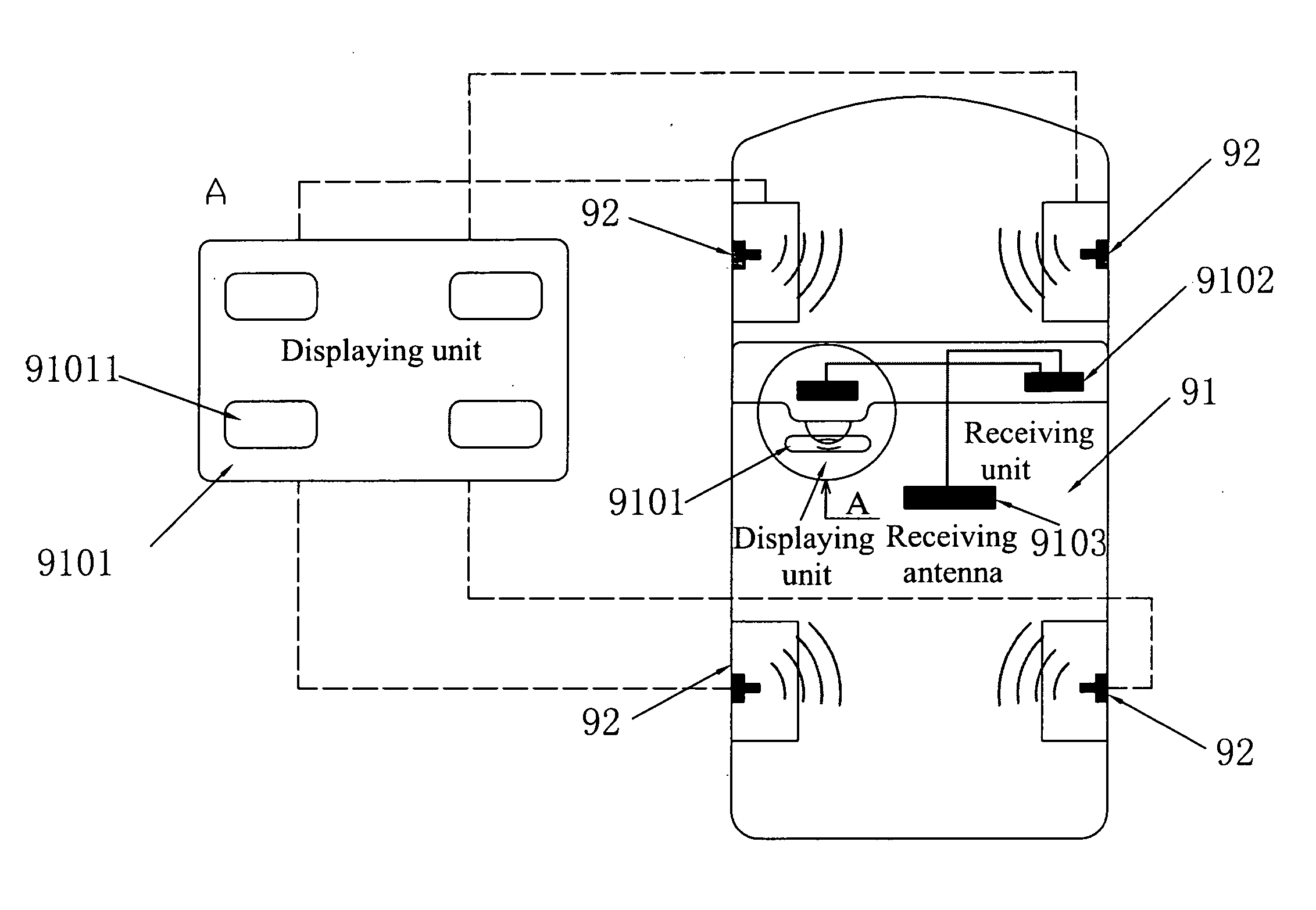
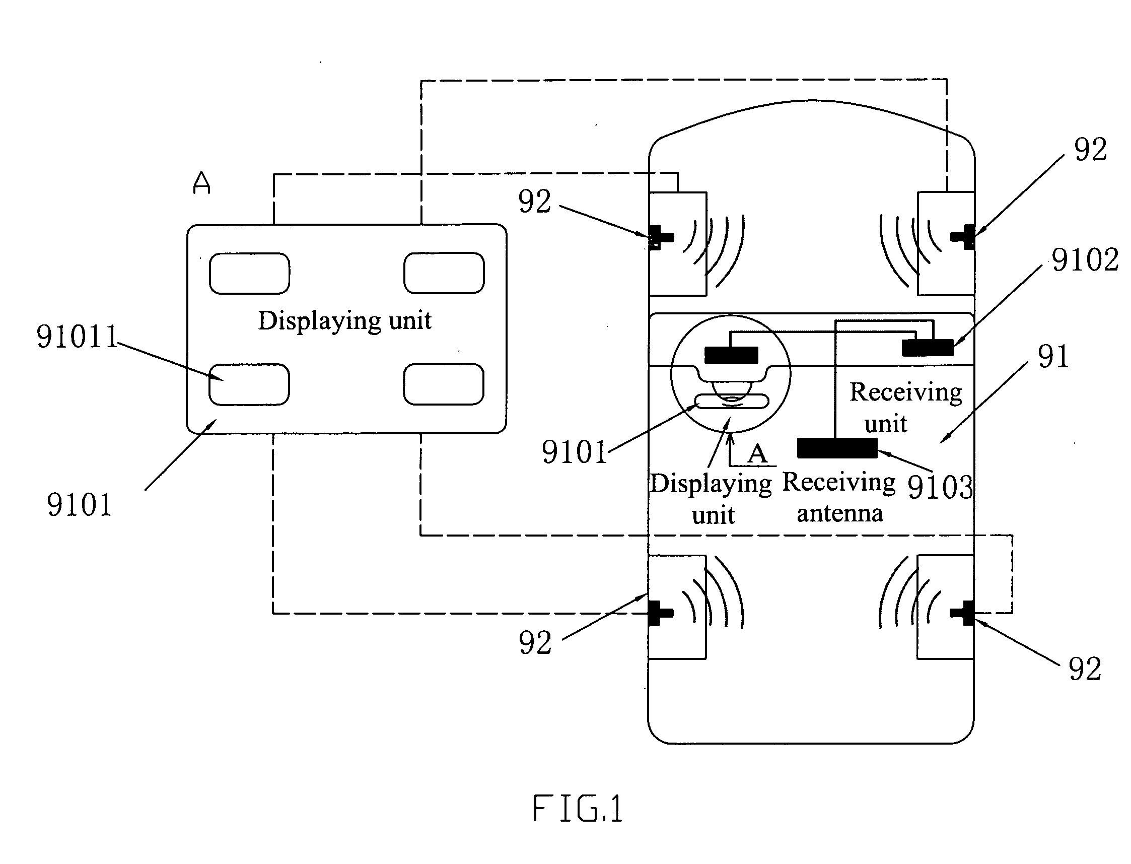
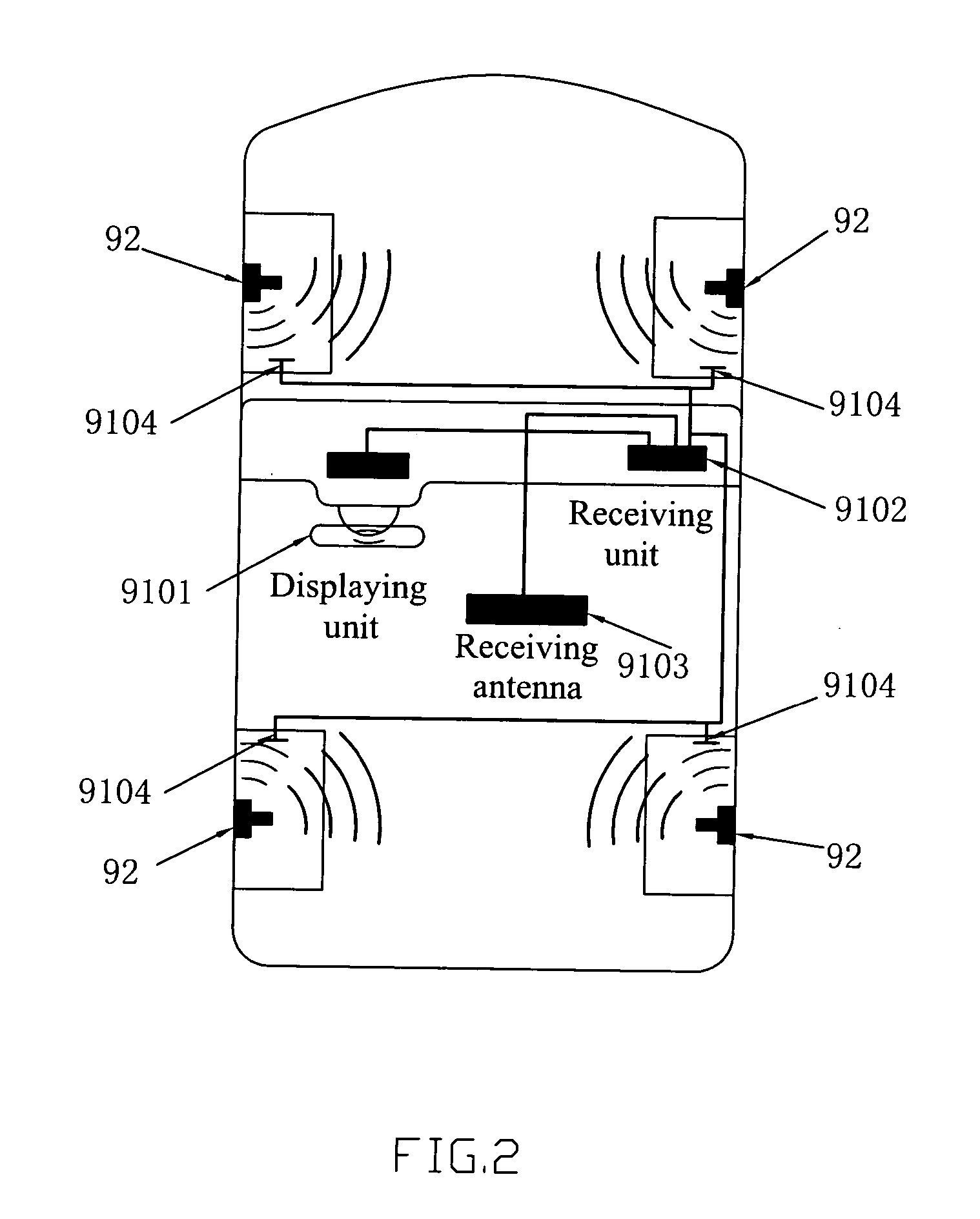
[0076] As mentioned above, receiving and display unit 11 includes a display unit 101, a receiving unit 102 and a receiving antenna 103, which are connected by signal interface.

[0077] In this example, the circuit of the receiving unit 102 contains three parts: a power supply circuit, a receiving circuit 102a, and a data receiving interface circuit 102b. The function of power circuit is to provide power for the whole receiving and display unit, to start the unit automatically when the automobile is started, or to start the unit when the tire monitoring system is started. The function of the receiving circuit 102a is to receive, demodulate, decode and convert the RF signal 120 transmitted by antenna 123 and then send the converted display data to the data receiving interface circuit 102b, which in turn sends the received data to display un...

example 3

[0079]FIG. 7 shows a circuit principle of display unit 101 of receiving and display unit 11 according to the present invention.

[0080] In the example, the circuit of display unit 101 includes the following; a main control unit 101C, a code plug interface circuit 10145, a data displaying interface circuit 1011a and an alarm circuit 1011b.

[0081] In the figure, data receiving interface circuit 102b receives signals from receiving unit 102 and transmits them to display unit 101 for processing.

[0082] The received signal 120 is processed by main control unit 101C as follows: First, main control 25 unit 101C reads information, especially the ID code, then compares the received ID to the ID code obtained from code plug interface circuit 10145. If the IDs do not match, the received data is discarded and the next signal from data receiving interface circuit 102b is waited for. If the IDs match, the processing will continue, i.e., the data will be transmitted to data display interface unit 1...


PUM


Abstract

A kind of automobile tire pressure monitoring system and tire identification method consist of a transmitting & detecting unit, with one set on each tire, as well as a receiving & displaying unit including a receiving unit, a main control unit and a displaying unit. A plug-in encoding memory is plugged into the receiving & displaying unit. One fixed ID code, which is the same as that for the above encoding memory, is available for each transmitting & detecting unit. When the power is on, the receiving & displaying unit reads the ID code in each plug-in encoding memory plugged into the socket of the displaying unit, and saves the information on the corresponding relationships between ID codes saved in memories and the tire identity. After receiving the signal from the transmission unit, it reads the ID codes in it, and judges whether these codes are identical with those in memories. If the signal is valid, the receiving & displaying unit compares the corresponding relationships, judges on which tire the detection unit is transmitting the signal, and displays the information about pressure and temperature on corresponding areas.

Description

TECHNICAL FIELD [0001] The present invention relates to automobile tire monitoring systems and in particular to automobile tire pressure monitoring systems. The present invention is more specifically directed to a tire pressure monitoring system which uses a plug-in external encoding memory to identify each tire. BACKGROUND OF THE INVENTION [0002] Tire Pressure Monitoring Systems, abbreviated as TPMS, are mainly used to automatically monitor tire pressure and provide an early warning of low tire pressure caused by air leakage or high tire pressure caused by high temperature so as to avoid tire rupture and ensure safety driving. [0003] Generally, a tire pressure monitoring system consists of a transmitting and detecting unit (one for each tire) and a receiving and display unit (only one): [0004] The circuit of the transmitting and detecting unit consists of a temperature and pressure sensor, a MCU (Main Control Unit), a transmitter, and a battery. The unit includes a protective casin...

Claims


Application Information

Patent Timeline
IPC IPC(8): B60C23/00B60C23/02B60C23/04G06K19/00
CPCB60C23/0401B60C23/0416B60C23/0433G06K17/00B60C23/00G06K19/00G06K7/00
Inventor LI, WEICHEN, HONGLING
Owner BAOLONG HUF SHANGHAI ELECTRONICS CO LTD
Why Eureka
Try Eureka