
Method for converting an analog input signal, and analog-to-digital converter

Active Publication Date: 2006-08-24
APPLE INC
View PDF9 Cites 1 Cited by
  • Summary
  • Abstract
  • Description
  • Claims
  • Application Information

AI Technical Summary

Benefits of technology

[0012] One embodiment of the invention includes a method for converting an analog input voltage signal into a digital value by means of successive approximation which functions in a manner free of errors even at high clock rates. Furthermore, it can provide an analog-to-digital converter which operates even at low supply voltages and high clock rates.
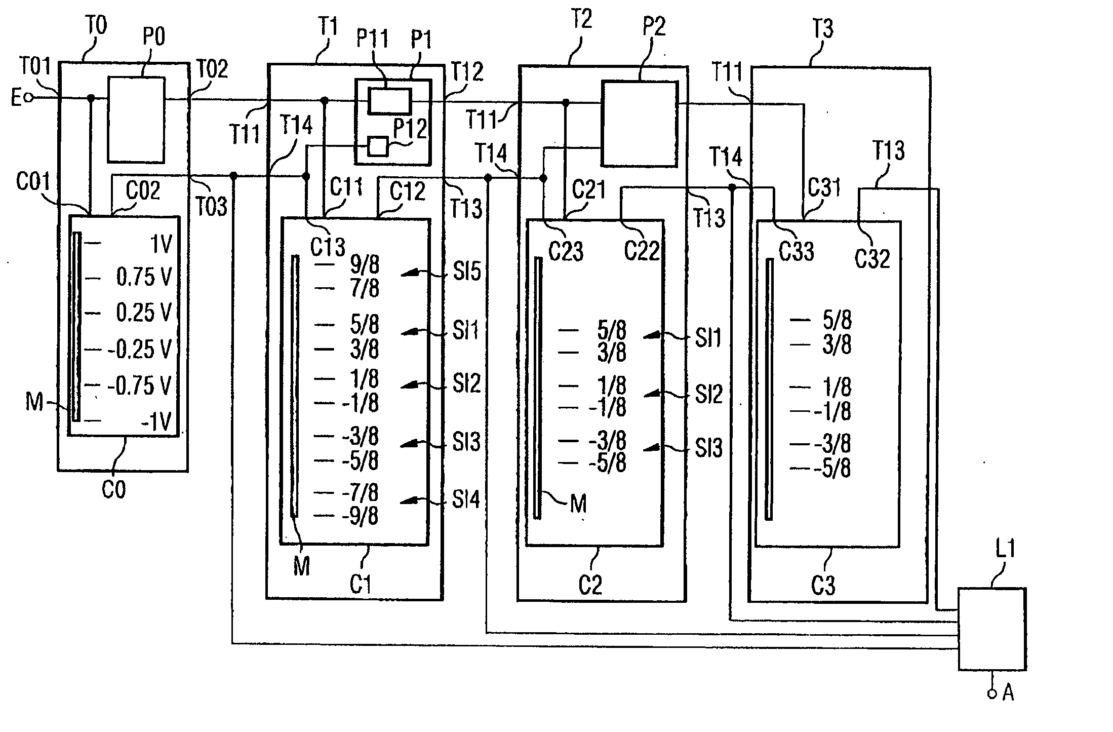
[0014] By virtue of the initial comparison, signals having a large amplitude are processed in a manner free of errors and the dynamic range for the input signal is increased. In addition, the control signal of the initial comparison is used to select a reference potential pair from a set of at least five reference potential pairs for the comparison operation of the first approximation. Consequently, a preselection is already made, and the comparison operation of the first approximation thereby acquires enough time for its decision-making. The method according to the invention is therefore particularly suitable even for high clock rates.
[0016] By virtue of the design of the analog-to-digital converter with a comparison means in each converter stage, a decision about an output signal to be generated by a converter stage is taken as early as in the converter stage connected upstream of the converter stage. At the same time, a preselection about the partial reference potentials used by the comparison means is already made by means of the control signal of the converter stage connected upstream. As a result, a longer period of time is made available to a comparison means for the comparison of the signal at the signal input. Conversely, an analog-to-digital converter according to the invention that is operated in clocked fashion can operate with significantly higher clock rates. The comparison with four partial reference potentials in the first converter stage additionally means that a large input signal is processed in a manner relatively free of errors even at small supply voltages of the analog-to-digital converter. It is therefore possible to reduce the supply voltage and to implement the analog-to-digital converter using current-saving CMOS circuit technology.
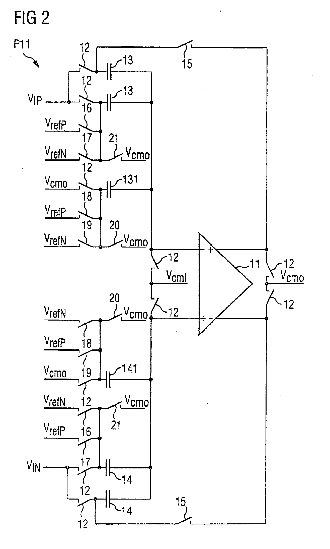
[0036] In one refinement of the invention, the first converter stage has a sample-and-hold circuit. The signal input of the first converter stage is connected to the output of a sample-and-hold circuit which is designed for sampling an input voltage signal during the sample phase and for outputting a signal at the output of the first converter stage during the hold phase. In this case, the value of the voltage signal output is equal to the value of the input voltage signal during the sample phase. Possible errors in the conversion of an analog signal into a digital signal can thus be reduced.

Problems solved by technology

Rising clock rates lead to problems, however, in sample-and-hold circuits in the individual approximation stages of the analog-to-digital converter.
At low clock rates, a short period of time between the sample phase and the hold phase is sufficient for decision-making, but at high clock rates the period of time is too short and the error rate rises greatly.
The major disadvantage of the analog-to-digital converter described therein, however, is its power consumption and its high supply voltage of 3.3 V, which is at odds with the requirement for a lower power consumption and small supply voltage.
In addition, the problem of an excessively short period of time for decision-making is not solved completely in the case of this analog-to-digital converter.
However, the problem of an error-free conversion remains in this case, too.

Method used


Image

  • Method for converting an analog input signal, and analog-to-digital converter
  • Method for converting an analog input signal, and analog-to-digital converter
  • Method for converting an analog input signal, and analog-to-digital converter

Examples


Embodiment Construction

[0045] One or more aspects and / or embodiments of the present invention are described with reference to the drawings, wherein like reference numerals are generally utilized to refer to like elements throughout, and wherein the various structures are not necessarily drawn to scale. In the following description, for purposes of explanation, numerous specific details are set forth in order to provide a thorough understanding of one or more aspects of the present invention. It may be evident, however, to one skilled in the art that one or more aspects of the present invention may be practiced with a lesser degree of these specific details. In other instances, known structures and devices are shown in block diagram form in order to facilitate describing one or more aspects of the present invention.

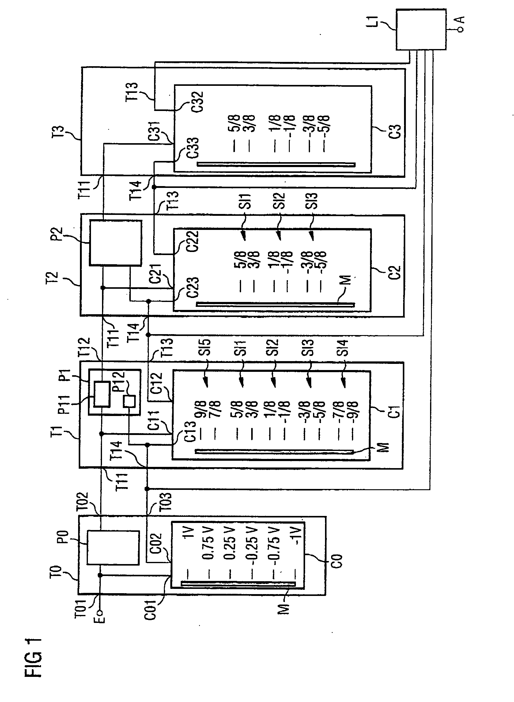
[0046]FIG. 1 shows an analog-to-digital converter having an input E and an output A. An analog input voltage signal is fed in at the input E of the analog-to-digital converter, the converted di...


PUM


Abstract

A method for converting an analog input signal into a digital value with successive approximation. A first comparison operation is provided before a first approximation, which subdivides a predefined input voltage interval into five partial intervals according to four reference potentials. During the comparison operation, a partial voltage interval determined is used in the ensuing approximation for the selection of a new reference potential pair to be used. This method enables higher sampling rates. At the same time, the range of the input signal is increased.

Description

REFERENCE TO RELATED APPLICATIONS [0001] This application is a continuation of PCT / DE2004 / 001587, filed Jul. 21, 2004 which was not published in English, that claims the benefit of the priority date of German Patent Application No. DE 10337042.0, filed on Aug. 12, 2003, the contents of which both are herein incorporated by reference in their entireties.FIELD OF THE INVENTION [0002] The invention relates to a method for converting an input signal into a digital value by means of successive approximation. The invention furthermore relates to an analog-to-digital converter for converting an analog input signal into a digital value. BACKGROUND OF THE INVENTION [0003] Analog-to-digital converters are important components in digital signal processing. In this case, analog-to-digital converters convert the voltage of an input signal into a number proportional thereto, which is output as a digital signal. The digital signal is often a serial sequence of a number of bits, the binary value of...

Claims


Application Information

Patent Timeline
IPC IPC(8): H03M1/12H03M1/14H03M1/44
CPCH03M1/146H03M1/44
Inventor STROBLE, OLAFDIAS, VICTOR
Owner APPLE INC
Learn More