
Compact image capture assembly using multiple lenses and image sensors to provide an extended zoom range

a technology of image sensor and image sensor, which is applied in the field of digital cameras, can solve the problems of increased size of digital camera, increased cost of large zoom range lens, user inconvenience, etc., and achieves the effects of compromising optical quality, large size, and high cos

Active Publication Date: 2006-08-24
APPLE INC
View PDF21 Cites 67 Cited by
  • Summary
  • Abstract
  • Description
  • Claims
  • Application Information

AI Technical Summary

Benefits of technology

[0016] The object of this invention is to provide an extended zoom range in a digital camera without unduly increasing the size or cost of the camera.
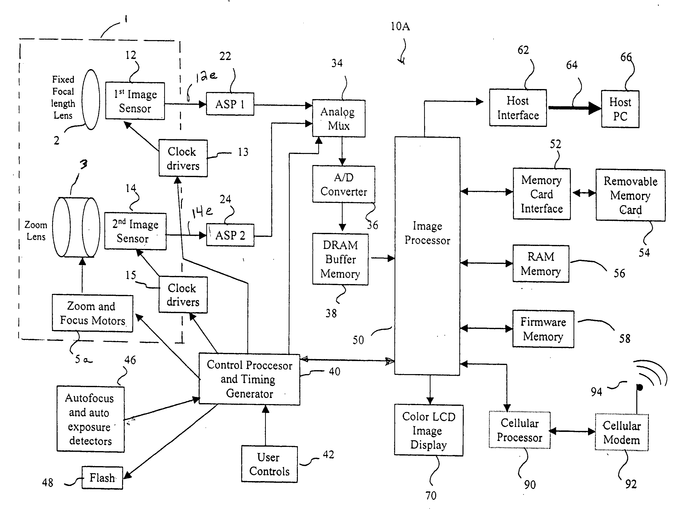
[0020] These various aspects of the invention provide significant technical advantages. By providing a plurality of optical image capture modalities within a digital camera, wherein each modality includes a lens-sensor combination with a distinctive different focal length or combination of focal lengths (i.e., a zoom), the conflicted requirements (namely, large size, high cost and compromised optical quality) engendered by digital camera consumer desire for a large zoom ratio, e.g., 10:1, can be accomplished in a smaller scale space at lower cost with higher quality optical results than heretofore achieved.

Problems solved by technology

Unfortunately, providing a large zoom range lens, without sacrificing the quality of the captured images, increases the size of the digital camera.
Large zoom range lenses are also more costly.
With higher cost cameras, such as single lens reflex cameras, these problems are sometimes addressed by using multiple interchangeable zoom lenses, such as two 3:1 zoom lenses, e.g., a 28-70 mm zoom and a 70-210 zoom.
Such an option, which has its own problems in user inconvenience, is nonetheless not available for low cost digital cameras.
However, in the case of a digital still camera or especially in the case of mobile phone digital camera, lens modules are required to be extremely small due to the limited space for the lens module.
Such cameras, however, are not useful in the environment of the present invention because the lenses are not collecting images from the same scene.
This system, of course, is an alternative to a single optical zoom lens, whose usage the patent disclosure discourages as they (optical zooms) are lower quality, more expensive and mechanically more complex than fixed focal length lenses.
However, the inherent drawback of an electronic zoom is also low quality since the resolution of the electronic zoom feature ordinarily is limited by the number of scan lines available for zooming.
None of these prior art systems, and especially the multifocal length prior art systems, provide a sufficiently compact, low cost, large zoom range optical system for a small, lightweight and relatively inexpensive consumer digital camera.

Method used


Image

  • Compact image capture assembly using multiple lenses and image sensors to provide an extended zoom range
  • Compact image capture assembly using multiple lenses and image sensors to provide an extended zoom range
  • Compact image capture assembly using multiple lenses and image sensors to provide an extended zoom range

Examples


first embodiment

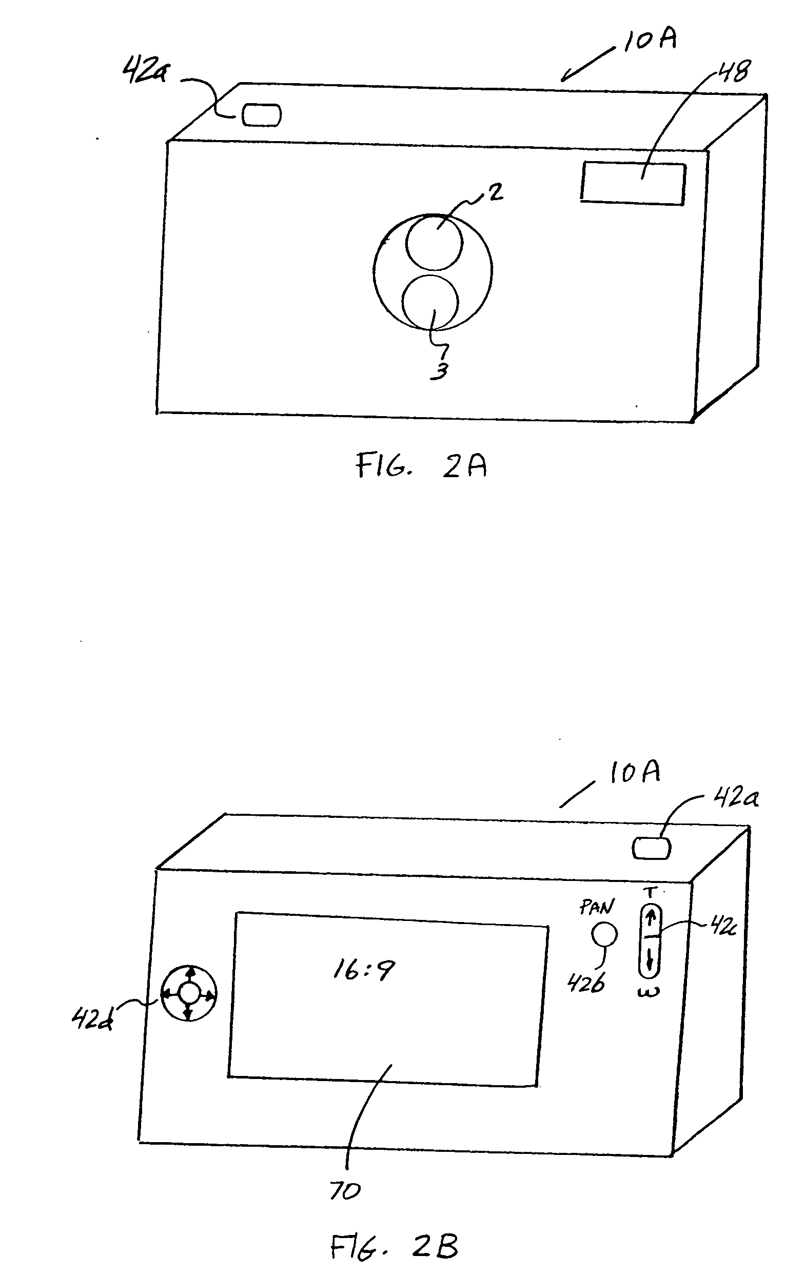
[0057]FIG. 11 provides a spatial layout of a digital camera, showing how the various components described in FIG. 10A fits within the confined space of the digital camera 10A. For example, FIGS. 11 and 12 show how the image capture assembly 1 is arranged within the width-wise dimension 201 of a digital camera 10A for the first embodiment shown in FIG. 10A. FIG. 11 is a frontal view of the digital camera 10A showing how the fixed focal length lens subassembly 1 a and the zoom lens subassembly 1b are positioned to one side of the lenses 2 and 3 beneath an electronic flash 48. A battery compartment 204 is located on the other side of the lenses 2 and 3. FIG. 12 is a top view of the digital camera 10A taken along lines 12-12 in FIG. 11, and further shows the location of a removable memory card 54 and a color LCD image display 70. FIG. 13 is a side view of the digital camera 10A taken along the lines 13-13 in FIG. 12, and further shows the vertical spacing of the fixed focal length lens ...

third embodiment

[0090]FIG. 8B is a rear view of the camera 10C, and similar in all respects to FIG. 2B. In a further (optional) variation of the third embodiment, the aspect ratio (e.g., 16:9) of the image provided by the fixed focal length lens 2 may be different than the aspect ratio of the image provided by the zoom lenses 3 or 4. In this case, as was shown in FIG. 2B, the user control 42 (e.g., the zoom button 42c) may input user commands for changing the aspect ratio of the image sensor 2 in order to obtain a variable panoramic effect that transitions from the wide angle of the lens 2 toward a narrower angle approaching the effect of the 4:3 aspect ratio of the zoom lens 3.

[0091]FIG. 9 depicts a flow diagram showing a method for capturing digital images using the digital camera of FIG. 7. This figure is mostly a composite of the blocks in FIGS. 3 and 6, and most of the blocks retain the same reference characters for the same block functions and steps. In lens setting block 100, when the camera...


PUM


Abstract

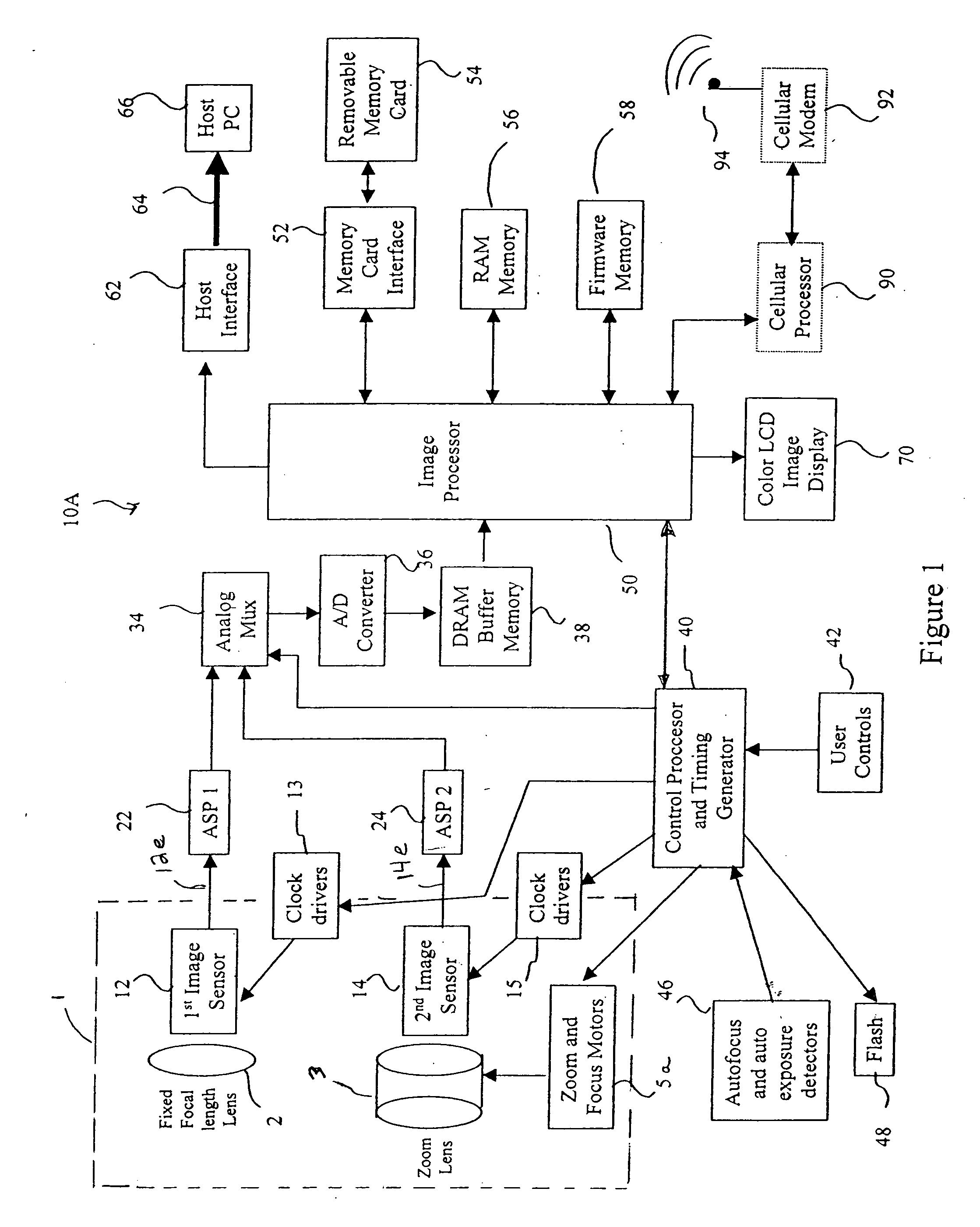
An optical image capture assembly for use in an electronic camera includes a first image sensor for generating a first sensor output; a first lens for forming a first image of the scene on the first image sensor; a second image sensor for generating a second sensor output; and a zoom lens for forming a second image of the scene on the second image sensor. The camera is contained within an enclosure and, in one variation of the assembly, either the first lens or the zoom lens (or both) forms its image through a folded optical system in which an optical path between the lens and its respective image sensor is folded at an angle in order to conserve space within the enclosure.

Description

FIELD OF THE INVENTION [0001] The present invention relates to a digital camera that produces digital image files and, more particularly, to a digital camera that uses multiple lenses and image sensors to provide an extended zoom range. BACKGROUND OF THE INVENTION [0002] Currently, most digital cameras use a zoom lens and a single color image sensor to capture still and motion images. The captured images are then digitally processed to produce digital image files, which are stored in a digital memory in the camera. The digital image files can then be transferred to a computer, displayed, and shared via the Internet. The digital camera can be included as part of a mobile telephone, to form a so-called “camera phone”. The camera phone can transmit the digital image files to another camera phone, or to service providers, via a mobile telephone network. [0003] Small camera size and a large “optical zoom range” are two very important features of digital cameras. Users prefer to have a la...

Claims


Application Information

Patent Timeline
IPC IPC(8): H04N5/225
CPCH04N5/2254H04N5/2259H04N5/23209H04N5/23212H04N5/23241H04N23/55H04N23/58H04N23/663H04N23/67H04N23/651H04N23/843
Inventor LABAZIEWICZ, PETERJANSON, WILBERT F. JR.PARULSKI, KENNETH A.
Owner APPLE INC
Learn More