Data storage device

Inactive Publication Date: 2006-08-24
IBM CORP
View PDF11 Cites 19 Cited by
  • Summary
  • Abstract
  • Description
  • Claims
  • Application Information

AI Technical Summary

Benefits of technology

[0014] According to a third aspect of the invention, a method for operating the storage device is claimed comprising the step of varying a voltage potential applied to the capacitive platform depending on a desired distance between the tip and the storage medium, or on a desired force exerted by the tip apex on the storage medium, and grounding the second electrode. In that way it is possible to control the distance and/or the force individually for each probe or for a group of p

Problems solved by technology

The heater cantilever is supplied with an amount of electrical energy, which causes the probe to heat up to a temperature that is not high enough to soften the polymer layer as is necessary for writing.
Therefore, it is a challenge to pr

Method used


Image

  • Data storage device
  • Data storage device
  • Data storage device

Examples


Embodiment Construction

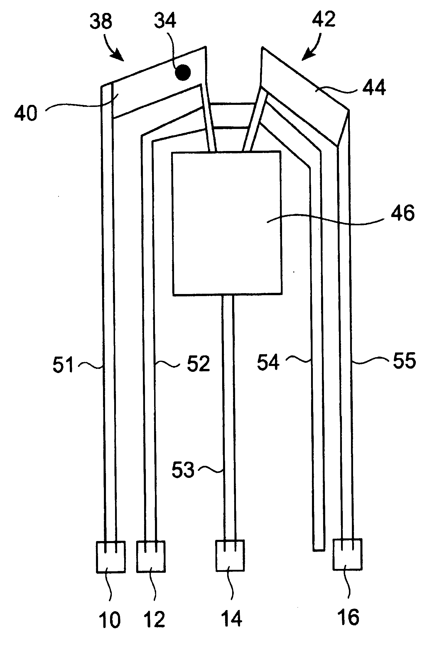
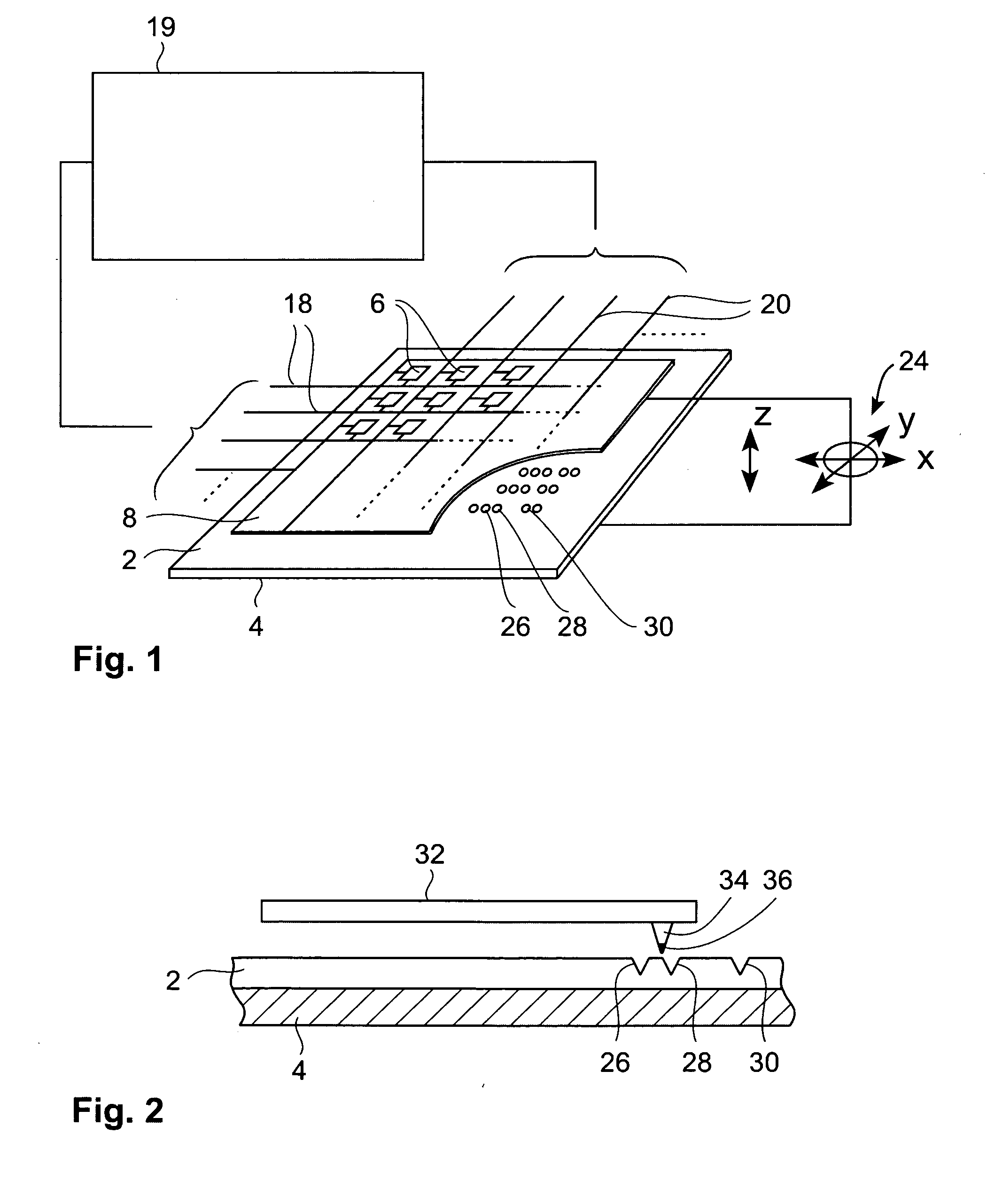
[0051] The present invention provides a storage device comprising a storage medium for storing data in the form of marks, e.g. topographic or magnetic marks but not necessarily limited to these. At least one probe is mounted on a common frame; the common frame and the storage medium are designed for moving relative to each other for creating or detecting the marks. The marks represent data, preferably logical “1”s whereas the absence of marks preferably represents logical “0”s.

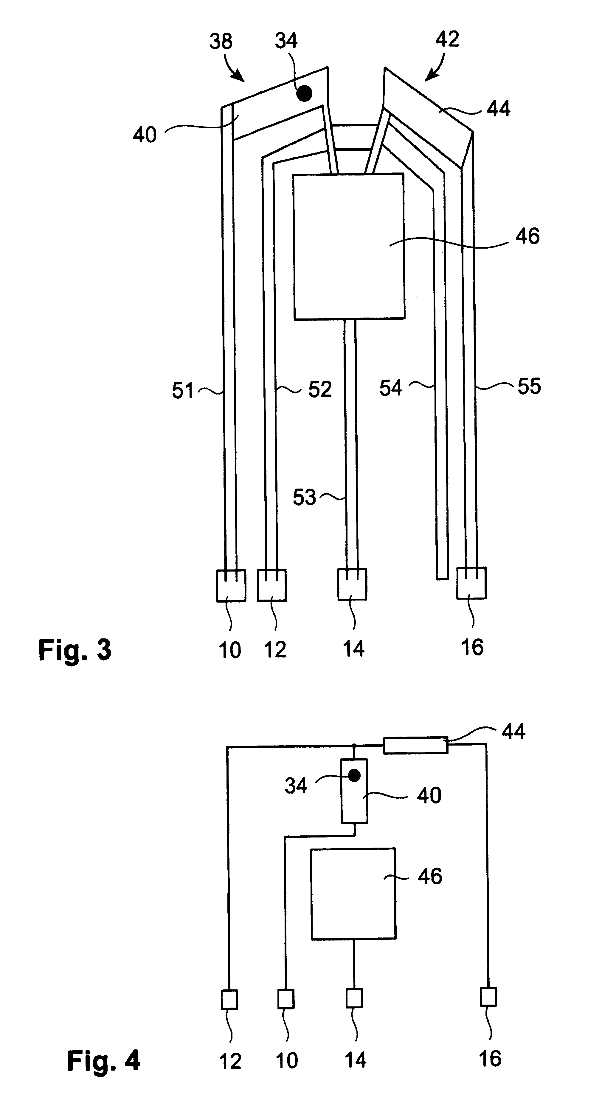
[0052] Each probe comprises a tip with a nanoscale apex facing the storage medium, a read sensing element and a write element. Each probe further comprises a capacitive platform, which forms a first electrode and is designed so that a voltage potential can be applied to the capacitive platform, which is independent from a control signal for the read sensing element and which is independent from a control signal for the write element. The capacitive platform may physically be formed from more than one part. A ...


PUM


Abstract

A storage device including a storage medium for storing data in the form of topographic or magnetic marks. At least one probe is mounted on a common frame, the common frame and the storage medium designed for moving relative to each other for creating or detecting said marks. Each probe includes a tip facing the storage medium, a read sensing element, a write element and a capacitive platform, that forms a first electrode and is designed for a voltage potential applied to it independent from a control signal for said read sensing element and for said voltage potential applied to said capacitive platform being independent from a control signal for said write heating element. It further comprises a second electrode arranged in a fixed position relative to the storage medium forming a first capacitor together wherein said first electrode and a medium between the first and second electrode.

Description

TECHNICAL FIELD [0001] The present invention relates to a storage device for storing data and a method for operating a storage device. BACKGROUND OF THE INVENTION [0002] In the field of this invention techniques are known that use nanometer sharp tips for imaging and investigating the structure of materials down to the atomic scale. Such techniques include atomic force microscopy (AFM) and scanning tunneling microscopy (STM), as disclosed in EP 0 223 918 B1 and U.S. Pat. No. 4,343,993. [0003] Based on the developments of the scanning tunneling microscopy and the atomic force microscopy, new storage concepts have been introduced over the past few years profiting from these technologies. Probes having a nanoscale tip are being introduced for modifying the topography and for scanning an appropriate storage medium. Data are written as sequences of bits represented by topographical marks, such as indentation marks and non-indentation marks. The tips comprise apexes with a radius in the l...

Claims


Application Information

Patent Timeline
IPC IPC(8): G11B9/00
CPCB82Y10/00G11B9/1472G11B11/007
Inventor BAECHTOLD, PETERBEDNORZ, JOHANNES G.BINNIG, GERD K.CHERUBINI, GIOVANNIELEFTHERIOU, EVANGELOS S.DESPONT, MICHEL
Owner IBM CORP
Why Eureka
Try Eureka