Method for utilizing dry film

a technology of dry film and film spherical, which is applied in the field of dry film spherical, can solve problems such as degrading production yield, and achieve the effect of excellent sequent production yield and accurate exposur

Inactive Publication Date: 2006-08-24
ADVANCED SEMICON ENG INC
View PDF3 Cites 3 Cited by
  • Summary
  • Abstract
  • Description
  • Claims
  • Application Information

AI Technical Summary

Benefits of technology

[0007] One object of the present invention is to provide a method for utilizing a dry film. After a dry film is pressed onto a substrate and before the exposure, a carrier film with light transmission of the dry film is cleaned in a darkroom for removing the contaminant, such as residual photoresist and particles, on the carrier film. At the same time, the dry film burrs around the dry film may be removed. Thereby, an accurate exposure and an excellent sequent production yield are achieved.
[0008] Another object of the present invention is to provide a method for forming a photoresist on a wafer. In the method, a carrier film with light transmission is formed on a photoresist layer on an active area of a wafer, and thus the photoresist layer is protected from being removed when the carrier film and the wafer are cleaned.
[0010] According to the method for utilizing a dry film provided by the present invention, it comprises providing a dry film at least comprising a carrier film with light transmission and a photoresist layer. The film is pressed onto a substrate, such as a wafer, such that the photoresist layer is attached to the substrate. The carrier film of the dry film is cleaned in a darkroom for facilitating the sequent exposure and development. Generally, before the carrier film is cleaned, the dry film is firstly cut to a size corresponding to that of the substrate. The carrier film is cleaned for removing the contaminant, such as residual photoresist and particles, on the carrier film, and the dry film burrs on the edge of the dry film is removed simultaneously. Furthermore, in an embodiment, the step of cleaning the carrier film further includes chemical spraying, water rinsing, drying, and the like. And after the step of cleaning the carrier film, the edge of the photoresist layer of the dry film will shrink.

Problems solved by technology

However, when the dry film is pressed onto the wafer, the contaminant produced during the process may cause the inaccurate exposure and degrade the production yield.

Method used


Image

  • Method for utilizing dry film
  • Method for utilizing dry film
  • Method for utilizing dry film

Examples


Embodiment Construction

[0015] The method for utilizing a dry film provided by the present invention is applicable to a wafer level packaging process, and an embodiment is described below.

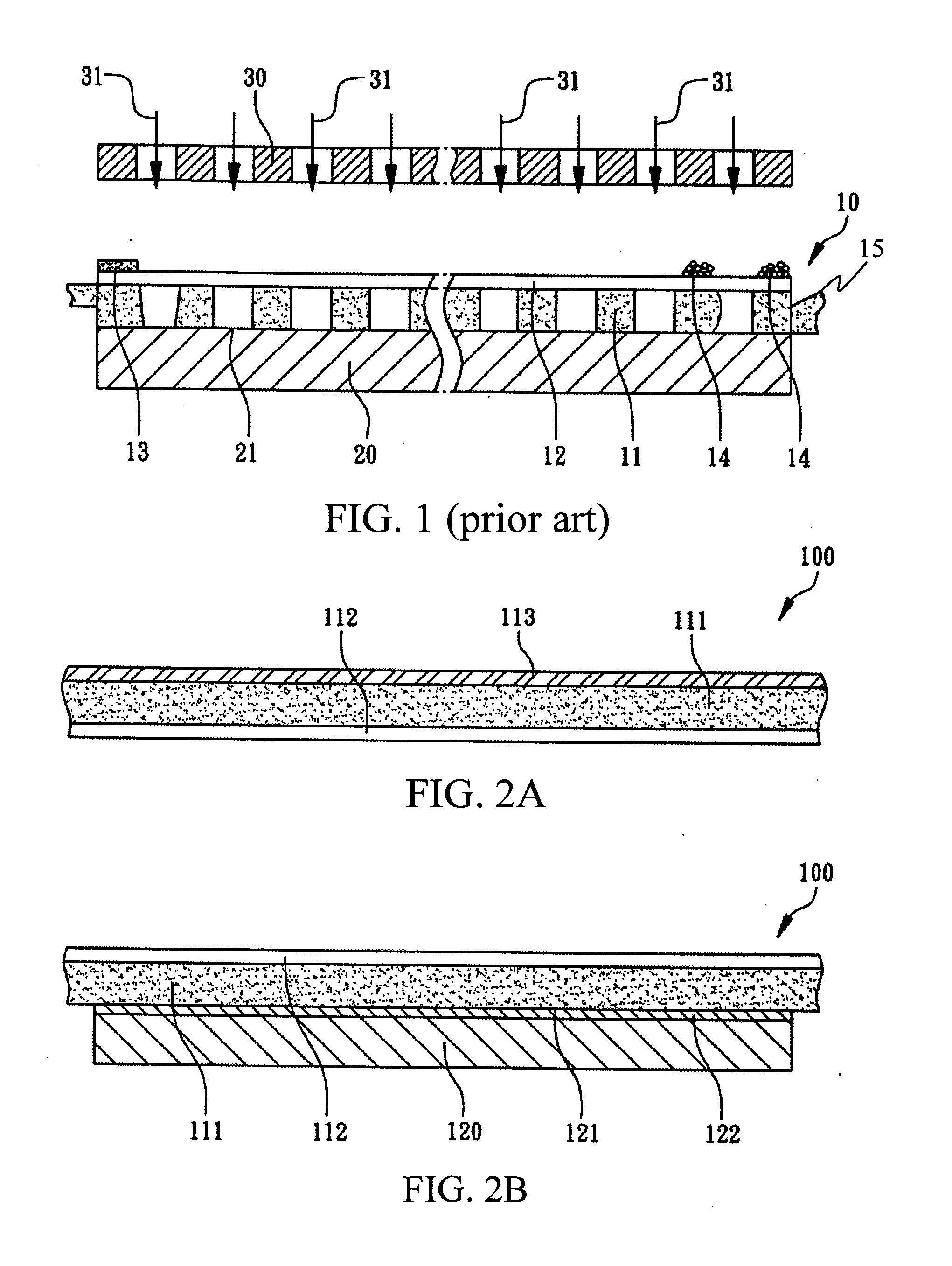
[0016] Firstly, with reference to FIG. 2A, a dry film 100 is provided. The dry film 100 comprises at least three layers, namely at least one photoresist layer 111, a carrier film 112 with light transmission, and a passivation film 113. The photoresist layer 111 is a kind of photosensitive resin and may be a positive photoresist or a negative photoresist. The photoresist layer 111 is formed on the carrier film 112 and covered by the passivation film 113. In the present embodiment, the photoresist layer 111 is a negative photoresist as a plating bump. Generally, the material of the carrier film 112 is PET, i.e., polyester, which is also referred to as Mylar film and the material of the passivation film 113 is PE, i.e., polyethylene.

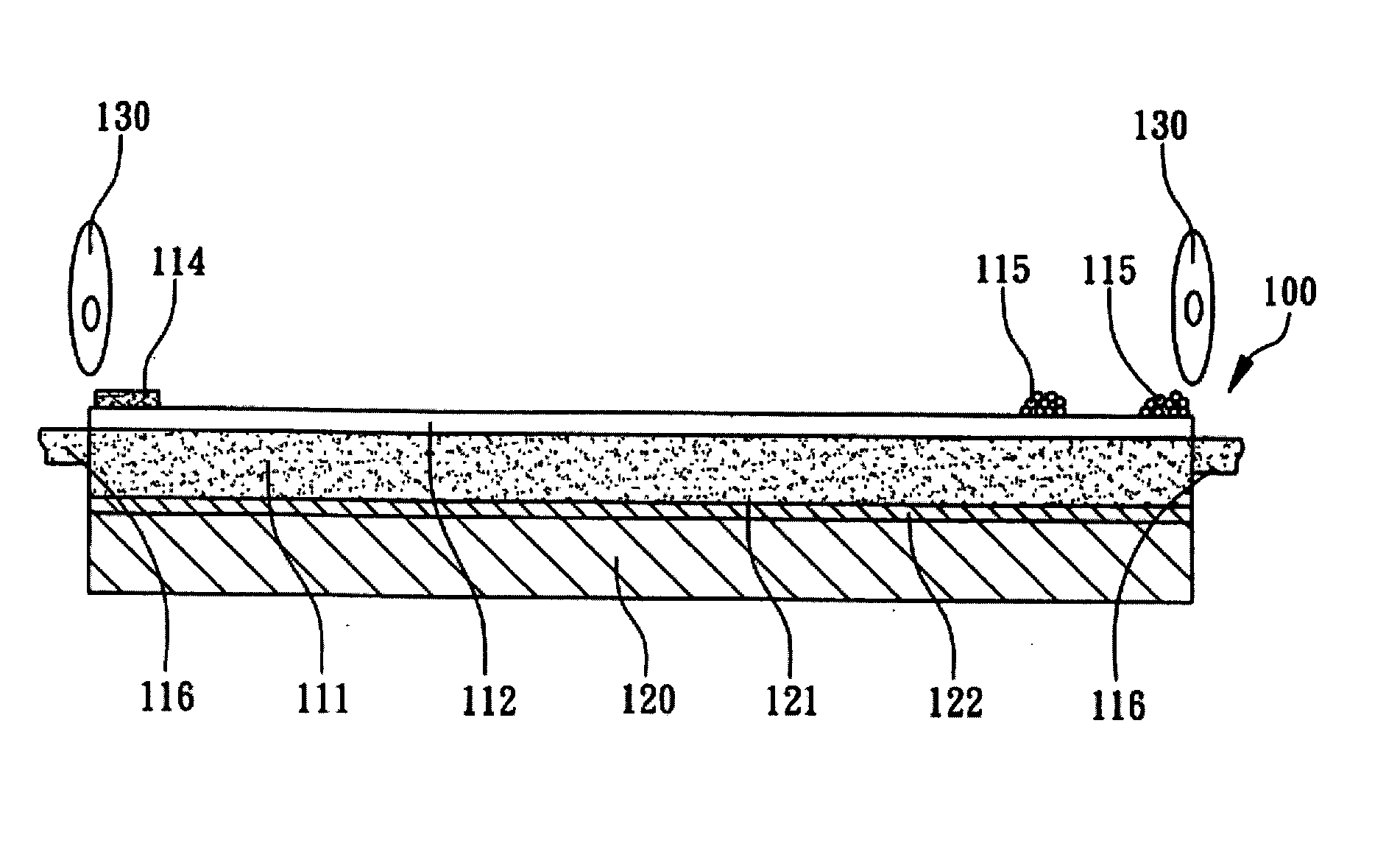
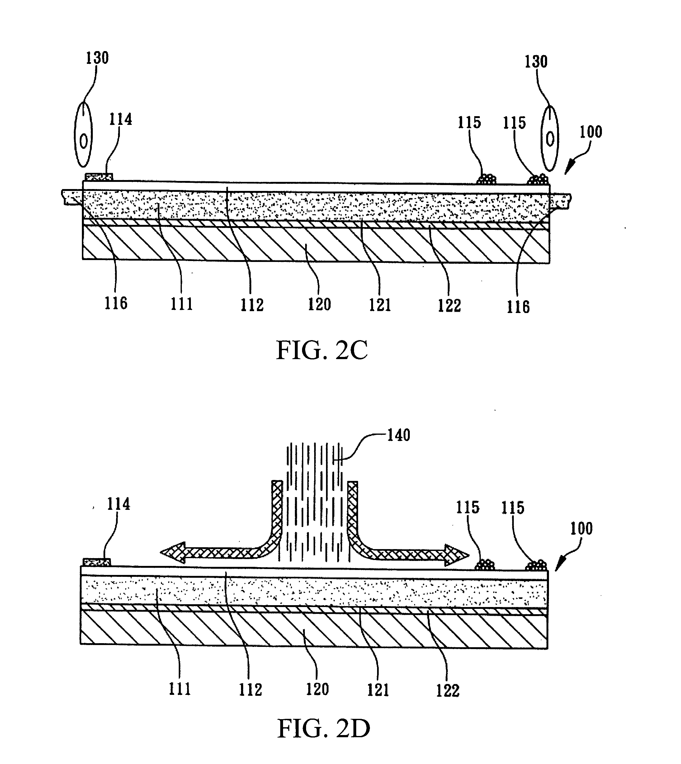
[0017] Subsequently, with reference to FIG. 2, the dry film 100 is pressed onto a substrate...


PUM

PropertyMeasurementUnit
active areaaaaaaaaaaa
areaaaaaaaaaaa
light transmissionaaaaaaaaaa

Abstract

A method for utilizing a dry film is provided. A dry film is pressed onto a substrate, such as a wafer. The dry film includes a photoresist layer tightly attached to the substrate and an exposed carrier film with light transmission. Before exposure and development, the carrier film of the dry film is cleaned in a darkroom, wherein the cleaning method may include a step of chemical spraying and a step of rinsing through DI water. Accordingly, the contaminant on the carrier film can be removed. In addition, the dry film burrs can be also removed. Thus, an excellent production yield for sequent exposure and development can be achieved.

Description

CROSS-REFERENCE TO RELATED APPLICATIONS [0001] This non-provisional application claims priority under 35 U.S.C. § 119(a) on Patent Application No. 094105479 filed in Taiwan, R.O.C. on Feb. 23, 2005, the entire contents of which are hereby incorporated by reference. BACKGROUND OF THE INVENTION [0002] 1. Field of Invention [0003] The present invention relates to a method for utilizing a dry film, and particularly, to an application method for pressing a dry film onto a substrate, such as a wafer, during a wafer level packaging process. [0004] 2. Related Art [0005] In the domain of the wafer level packaging, an image transfer is usually performed through photoresist materials for forming bumps or circuits on a wafer by depositing or etching. In order to achieve a suitable thickness and a favorable image effect, the currently employed photoresist material is dry films. The conventional dry film has a three-layer structure, comprising a carrier film with light transmission, at least one ...

Claims


Application Information

Patent Timeline
Patent Type & Authority Applications(United States)
IPC IPC(8): G03F7/00
CPCG03F7/161G03F7/168
Inventor TSENG, TSUNG-YENHUANG, MIN-LUNGTSAI, CHI-IONGYANG, MIN-CHIH
Owner ADVANCED SEMICON ENG INC
Why Eureka
Try Eureka