Knee implant

a technology for implants and knees, applied in knee joints, medical science, prostheses, etc., can solve the problems of long healing and rehabilitation periods, large components, and patient inability to quickly return to normal activities

Inactive Publication Date: 2006-08-24
MAKO SURGICAL CORP
View PDF4 Cites 270 Cited by
  • Summary
  • Abstract
  • Description
  • Claims
  • Application Information

AI Technical Summary

Benefits of technology

[0025] Another embodiment of the present invention relates to a method of implanting a prosthetic device. This method includes, among other possible steps: evaluating a knee of a patient including a previously implanted prosthetic device; implanting in the knee an additional componen

Problems solved by technology

A problem with a conventional implant procedure is that the components are relatively large.
Such large incisions tend to disrupt the tissues associated with the joint and its joint capsule, thereby requiring long healing and rehabilitation periods.
As a result, the patient can not quickly return to normal activities.
Although surgeons have recognized the desirability of minimizing the size of the incisions, the large size of the prostheses of current designs have frustrated attempts to use smaller incisions, e.g., 1-2 inches in length.
Further, when it is used to manage arthritis of the anterior and medial compartments (or the anterior and lateral compartments), Coon's prosthesis creates an abrupt transition on the lateral (or medial) compartment, thereby creating an interface of metallic implant and adjacent bone; this abrupt transition may promote degeneration in the non-implant region.
Moreover, the implant is excessively large with respect to the central portion of the knee.
Such a prosthetic device is not likely to provide long-term durability.
For example, as a result of the orientation of the femoral component parts, long-term cyclical loading on the component may cause the component to break.
Another problem associated with a conventional implant procedure is that it may require displacement of significant amounts of healthy bone.
Another problem with a conventional implant pro

Method used


Image

  • Knee implant
  • Knee implant
  • Knee implant

Examples


first embodiment

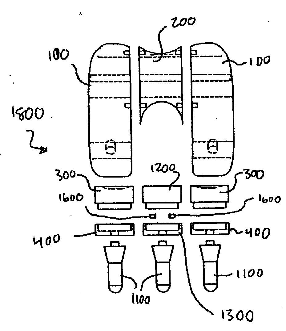
[0064]FIGS. 7A-7D are perspective, top, side, and front views, respectively, of a backing tray 400, which may be implanted in the medial region F of the tibia 40. A mirror image (shown in FIGS. 18A-18C) embodiment of the backing tray 400 can be implanted in the lateral region B of the tibia 40. Preferably, the backing tray 400 is formed of a strong biocompatible metal such as a cobalt-chromium alloy, a titanium alloy, or stainless steel. Additionally or alternatively, the backing tray 400 may be formed from a strong ceramic (e.g., an alumina, zirconia, or carbon-based ceramic), one or more high performance polymers, and / or one or more high performance polymer composites (e.g., a composite material made of nano particles of PTFE and PEEK; particle ratios can be either fixed or can vary in the range on 0-100% (and vice versa), thereby enabling gradual changes in material properties in the component). Additionally or alternatively, the component may be made of a material of the types d...

second embodiment

[0085] The depressions 206, 906 of the first and second embodiment center femoral components 200, 900 are configured to slidingly receive a patellar backing device 1000, which will now be discussed with respect to FIGS. 15A-15D. Preferably, the patellar backing device 1000 is formed of a strong biocompatible metal such as a cobalt-chromium alloy, a titanium alloy, or stainless steel. Additionally or alternatively, the patellar backing device 1000 may be formed from a strong ceramic (e.g., an alumina, zirconia, or carbon-based ceramic), one or more high performance polymers, and / or one or more high performance polymer composites (e.g., a composite material made of nano particles of PTFE and PEEK; particle ratios can be either fixed or can vary in the range on 0-100% (and vice versa), thereby enabling gradual changes in material properties in the component). Additionally or alternatively, the component may be made of a material of the types described in U.S. patent application Ser. No...


PUM


Abstract

A modular prosthetic device is provided for replacement of the knee. The device is assembled from a plurality of components, each of which can be inserted through a small incision. After inserting the components through the incision, the device can be assembled within the knee cavity. The modularity of the device enables a surgeon to replace only those regions of the knee that are diseased or damaged, thereby avoiding a complete knee replacement. If, at a later time, additional regions of the knee become diseased or damaged, those additional regions of the knee can be replaced by additional device components and those additional components can be connected to the previously implanted components. By replacing only those regions of the knee that are diseased or damaged and by implanting each of the components through the small incision, the surgery is minimally invasive and, therefore, requires reduced time for healing and rehabilitation.

Description

CROSS REFERENCE TO RELATED APPLICATIONS [0001] This application claims priority from U.S. Provisional Patent Application Ser. No. 60 / 655,013, filed Feb. 22, 2005, which is incorporated by reference herein.BACKGROUND OF THE INVENTION [0002] This invention relates to prosthetic devices for use in partial or complete knee replacement and associated methods. [0003] Partial or complete replacement of diseased and / or damaged knees with suitable prostheses has become a common surgical procedure. The outcome of such surgery has been found to be favorable in most cases, and the surgery has come to be regarded as a very favorable surgical intervention for restoring function to knees damaged by trauma or degenerative disease. Each year more than 650,000 patients worldwide undergo operations in which either part or all of a knee joint is replaced by an implant, which typically operates well for 10 or more years. [0004] Traditional implant designs include a tibial component and a femoral compone...

Claims


Application Information

Patent Timeline
IPC IPC(8): A61F2/38
CPCA61F2/38A61F2002/30604A61F2002/3895
Inventor CLEMOW, ALASTAIR J.T.MEARS, DANA C.
Owner MAKO SURGICAL CORP
Why Eureka
Try Eureka