Portable information device

a technology of information device and portability, applied in the field of portable information device, can solve the problems of limited power supply, inability to work fingerprint sensors, limited capacity of battery (power source) mountable on this card, etc., and achieve the effects of saving power consumption, driving for longer time, and efficient use of power

Inactive Publication Date: 2006-08-24
SEIKO EPSON CORP
View PDF11 Cites 31 Cited by
  • Summary
  • Abstract
  • Description
  • Claims
  • Application Information

AI Technical Summary

Benefits of technology

[0011] An advantage of the invention is to provide a portable information device that is capable of being driven for longer time by efficiently using power from its power source.
[0012] A portable information device according to a first aspect of the invention having a central processing unit (CPU) and a power source coupled to the CPU and driving the CPU includes: an external control system circuit provided between the power source and the CPU, and providing power supply from the power source to the CPU by an external input; and an autonomous control system circuit providing power supply from the power source to the CPU under control of the CPU. The external control system circuit and the autonomous control system circuit are coupled in parallel with each other. The external control system circuit includes a mechanical switch turned on and off by an external input, while the autonomous control system circuit includes a transistor switch turned on and off under control of the CPU.
[0013] While the portable information device of the present aspect is not in use, both the mechanical switch and the transistor switch are off and do not supply power to the CPU. The portable information device of the present aspect may further include an electronic processing circuit that processes the device. The CPU controls power supply to this circuit. Therefore, no power is supplied to the CPU and the electronic processing circuit while the device is not in use, which saves power consumption. The mechanical switch is pressed to enable this device. The switch stays on and provides power supply to the CPU while this switch is pressed. Once the mechanical switch is turned on and starts providing power supply to the CPU, the CPU commands the autonomous control system circuit to turn on the transistor switch. The transistor switch included in the autonomous control system circuit stays on at least during the period the CPU commands so, and provides power supply to the CPU during this period. Accordingly, the CPU secures power supply to itself by keeping the transistor switch included in the autonomous control system circuit on, while the mechanical switch stays on. In other words, even if the mechanical switch is on to provides power supply to the CPU and turned off thereafter, the CPU controls on and off of the transistor switch on its own. Accordingly, the CPU does not lack power when the mechanical switch included in the external control system circuit is turned off, and controls power supply for itself with the autonomous control system circuit. After determining that the device completes predetermined processing and shutting off the power source, the CPU commands the autonomous control system circuit to turn off the transistor switch.
[0014] The portable information device of the present aspect may further include a capacitance provided between a positive power source and a negative power source of the autonomous control system circuit and in parallel with the CPU. The capacitance stores electric charge, while the power source supplies power to the CPU via the external control system circuit or the autonomous control system circuit. As the CPU commands the autonomous control system circuit to shut off power supply and then the transistor switch shifts to an off status, the electric charge stored in the capacitance is supplied to the CPU, securing the normal operation of the CPU. Even when power supply from the power source becomes less as the transistor switch is turned off, the CPU can complete the command to completely turn off the transistor switch with power supplied by the capacitance. The capacitance needs to store enough power for the CPU to keep commanding the autonomous control system circuit to shut off power supply even after the transistor switch is completely turned off. As the CPU uses up the electric charge stored in the capacitance, the CPU becomes a stop status with no power supplied. The CPU stays completely off until the mechanical switch is turned on to make the external control system circuit restart providing power supply. Accordingly, when the mechanical switch is not turned on and the device is not in use, the CPU receives no power, which saves power consumption due to standby power of the device, for example. It is thus possible to efficiently use the power source of the device. Furthermore, since the device stops power supply to the CPU on its own, it is possible to prevent unnecessary power consumption because a user forgets to turn off the power source of the device. Also, the mechanical switch included in the portable information device of the present aspect is preferably on while being pressed and off when being released. Accordingly, the mechanical switch is turned on simply by pressing it with a finger. After releasing the finger from the switch, power supply to the device is automatically shut off as mentioned above. Therefore, operability of the device is enhanced.
[0015] The portable information device of the present aspect may incorporate an electronic processing circuit that processes the device. As the CPU determines that the device completes predetermined processing, the CPU first shuts off power supply to the electronic processing circuit to stop the circuit, and then commands the autonomous control system circuit to turn off the transistor switch. The portable information device of the present aspect may further include an identity authentication function device. The CPU controls power supply to this device. The device takes identity authentication information by a command from the CPU. The operation of this device is determined by the CPU as necessary. The device receives power from the power source via the CPU only during its operation period. When the device shuts off its processing, the CPU commands the autonomous control system circuit to stop power supply to itself after stopping power supply to the identity authentication function device as well as to the electronic processing circuit. The CPU stops power supply to the electronic processing circuit and the identity authentication function device after they complete their roles, so that they can complete their functions safely, thereby minimizing the risk of damaging the device. As the identity authentication function device, a fingerprint sensor may be used, for example. The addition of this function can enhance security of the device.

Problems solved by technology

Since this type of portable information device is powered by a battery or the like provided on the device, it has a limited power supply.
This kind of IC card (portable information device) is so small and thin that the capacity of the battery (power source) mountable on this card is limited.
However, the IC card according to the first example uses up its battery in a short time to the point that the fingerprint sensor is no longer able to work, since the sensor is always driven while the switch is on.
Accordingly, if this device is an IC card with a small battery capacity, it uses up its battery in a short time to the point that the sensor is no longer able to work.
As for the device according to the third example, it is structurally difficult to provide the lid on the IC card.
The IC card with a small battery capacity would consume its battery even in a standby status.
While the portable information device of the present aspect is not in use, both the mechanical switch and the transistor switch are off and do not supply power to the CPU.
Therefore, no power is supplied to the CPU and the electronic processing circuit while the device is not in use, which saves power consumption.
Accordingly, when the mechanical switch is not turned on and the device is not in use, the CPU receives no power, which saves power consumption due to standby power of the device, for example.

Method used


Image

  • Portable information device
  • Portable information device
  • Portable information device

Examples


first embodiment

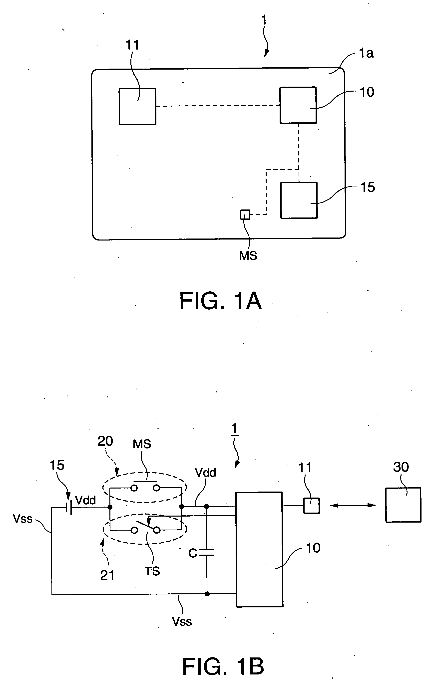
[0027]FIG. 1A is a plan view schematically showing the internal structure of an IC card (portable information device) according to a first embodiment of the invention. Referring to the view, this IC card 1 of the present embodiment includes a card substrate 1a, a central processing unit (CPU) 10 for arithmetic operations, a power source 15 coupled to the CPU 10 and serving as a battery to drive the CPU 10, an IC unit 11 controlled by the CPU 10, and a button-shaped micro (μ) switch (mechanical switch) MS that is turned on and off by external inputs. As the micro switch MS, a mechanical switch that is turned on when pressed and turned off when released is used here.

[0028]FIG. 1B is a schematic circuit diagram of the IC card 1 of the present embodiment.

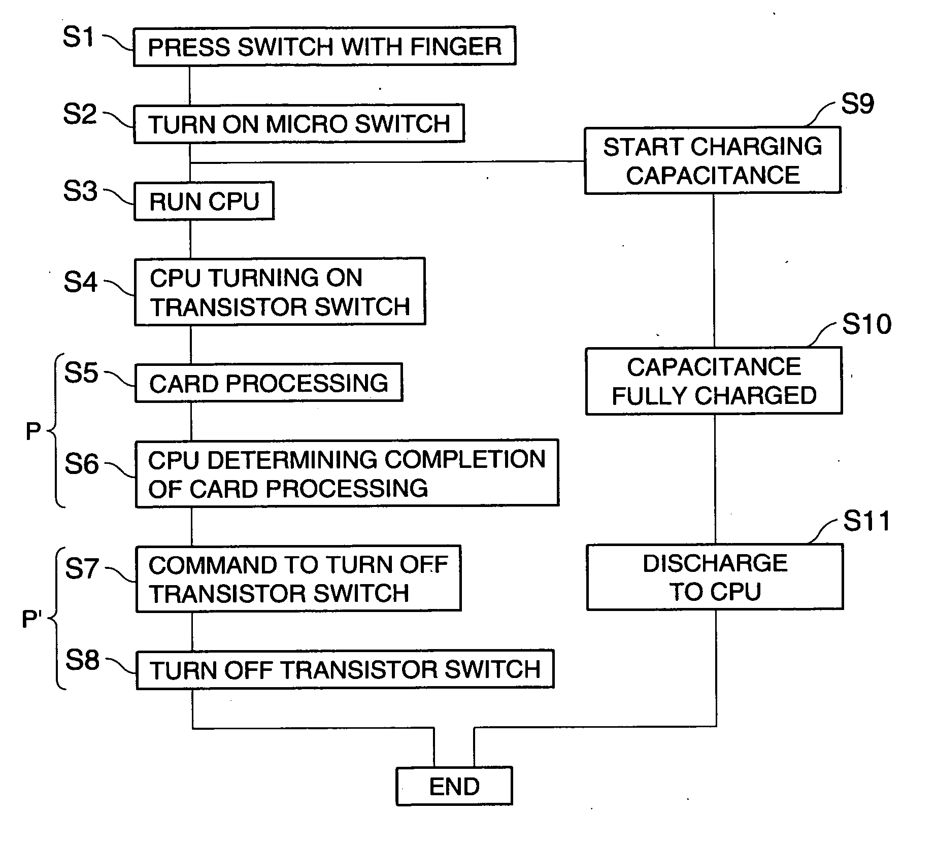
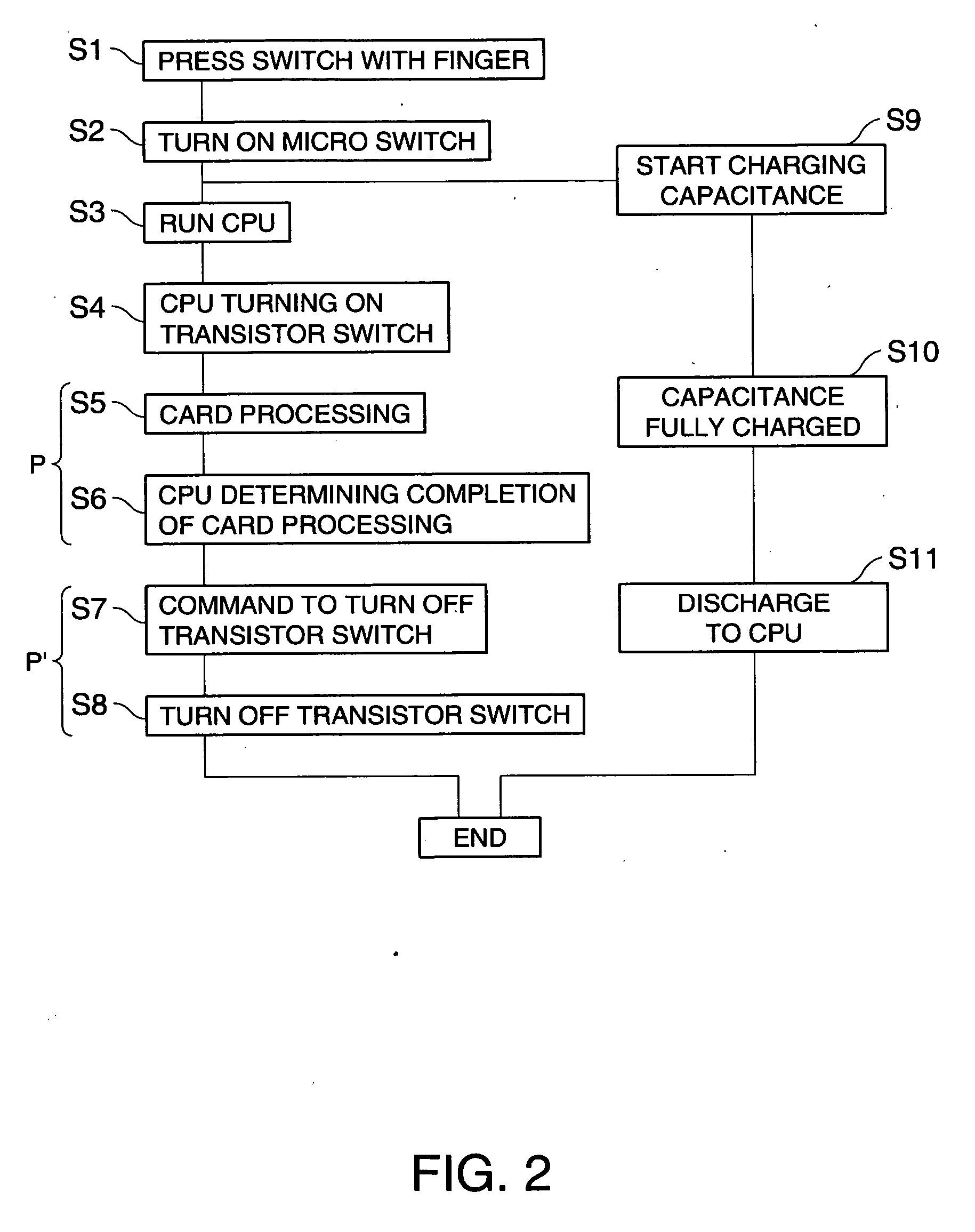
[0029] Referring to the diagram, provided between the power source 15 and the CPU 10 are an external control system circuit 20 that provides power supply from the power source 15 to the CPU 10 while the micro switch MS is pressed, and...

second embodiment

[0055] An IC card according to a second embodiment of the invention will now be described. The IC card of the present embodiment is provided by adding an electronic processing circuit to which power is supplied from the power source 15 under the control of the CPU to the IC card 1 of the first embodiment. Here, like numerals indicate like elements of the IC card 1, and like processes are omitted in a flowchart, which will be described later, and explanation thereof is simplified.

[0056]FIG. 3A is a plan view schematically showing the internal structure of the IC card of the present embodiment. Referring to the view, this IC card 2 includes an encryption unit 60 composed of an electronic processing circuit, which will be described in greater detail later, in addition to the elements of the IC card 1: the CPU 10, the power source 15, the IC unit 11 and the micro switch MS. This encryption unit 60 processes the IC card 2 as mentioned below.

[0057]FIG. 3B is a block diagram showing the ...

third embodiment

[0072] An IC card according to a third embodiment of the invention will now be described.

[0073] The IC card of the present embodiment is provided by adding a fingerprint detection unit 70 to which power is supplied from the power source 15 under the control of the CPU to the IC card 2 of the second embodiment. This unit serves as an identity authentication function device (electronic processing circuit). Here, like numerals indicate like elements of the IC cards 1 and 2, and like processes are omitted in a flowchart, which will be described later, and explanation thereof is simplified.

[0074]FIG. 5A is a plan view schematically showing the internal structure of the IC card of the present embodiment. Referring to the view, this IC card 3 includes a fingerprint detection unit 70 composed of an electronic processing circuit, which will be described in greater detail later, in addition to the elements of the IC card 2: the CPU 10, the power source 15, the IC unit 11, the micro switch M...


PUM


Abstract

A portable information device having a central processing unit and a power source coupled to the central processing unit and driving the central processing unit, comprises: an external control system circuit provided between the power source and the central processing unit, and providing power supply from the power source to the central processing unit by an external input; and an autonomous control system circuit providing power supply from the power source to the central processing unit under control of the central processing unit; the external control system circuit and the autonomous control system circuit being coupled in parallel with each other, the external control system circuit including a mechanical switch turned on and off by an external input, and the autonomous control system circuit including a transistor switch turned on and off under control of the central processing unit.

Description

BACKGROUND [0001] 1. Technical Field [0002] The present invention relates to a portable information device, such as an integrated circuit (IC) card. [0003] 2. Related Art [0004] Portable information devices having an identity authentication function to enhance security have been known in recent years. The function of identity authentication is achieved, for example, by providing a switch-driven fingerprint sensor on an IC card (portable information device) to take a user's fingerprint for authenticating the user. JP-A-2000-76412 is an example of related art. [0005] Since this type of portable information device is powered by a battery or the like provided on the device, it has a limited power supply. It is, therefore, desirable to extend the time for driving this device by efficiently using its battery. [0006] A technique has been developed to efficiently use power from the battery by providing a finger detection switch on the fingerprint sensor and making the device work only when ...

Claims


Application Information

Patent Timeline
Patent Type & Authority Applications(United States)
IPC IPC(8): H04L9/00
CPCG06K19/07G06K19/0705G06K19/0716G06K19/07345G06Q20/341G06Q20/40145G07F7/1008
Inventor MIYASAKA, MITSUTOSHI
Owner SEIKO EPSON CORP
Why Eureka
Try Eureka