Diaphragm, spherical-shell diaphragm and electroacoustic transducer, and method of manufacturing electroacoustic transducer

Active Publication Date: 2006-08-31
JVC KENWOOD CORP A CORP OF JAPAN
View PDF3 Cites 3 Cited by
  • Summary
  • Abstract
  • Description
  • Claims
  • Application Information

AI Technical Summary

Benefits of technology

[0018] Then, the present invention has been made in order to solve the above-described problems, and its object is to provide a diaphragm and an electroacoustic transducer that are capable of reducing generation of standing waves, obtaining a high sound-pressure even in a range of low-pitched sound, realizing highly efficient electroacoustic conversion of an input signal, specifying a reference direction for a radiated voice, and obtaining a uniform directivity in the circumferential direction.
[0019] Moreover, another object thereof is to provide a spherical shell diaphragm and an electroacoustic transducer that are capable of reducing generation of standing waves, reducing the number of peaks and dips, even if the diaphragm has a shape of a nearly spherical shell; unneccesitating a special bonding member; positioning easily in assembling; realizing especially high sound pressure even in a range of low-pitched sounds; and realizing a highly efficient electro-acoustic conversion of input signals.
[0020] Furthermore, yet another object is to provide a method of manufacturing an electroacoustic transducer configured by joining a plurality of polygonal segments with an elastic material to produce a polyhedron spherical shell diaphragm, the respective polygonal segment being to be driven by an individual driving section, the method being able to facilitate positioning of each section so that easy assembling is realized and to reduce characteristics variation.
[0064] According to the present invention, there may be provided an advantage that generation of standing waves is reduced, a high sound-pressure is obtained even in a range of low-pitched sound, a highly-efficient electroacoustic conversion of an input signal is enabled, a reference direction for a voice radiation is specified, and a uniform directivity in the circumferential direction is obtained.
[0065] According to the present invention, there may be brought about another advantage that generation of standing waves is reduced; a special bonding member is not required; positioning is easy upon assembling; high sound pressure may be obtained even in a range of low-pitched sounds; and a highly efficient electro-acoustic conversion of input signals may be enabled.
[0066] According to the present invention, there may be presented yet another advantage of simplified positioning of each section, easy assembling, and reduced variations in sound characteristics.

Problems solved by technology

However, it is somewhat disadvantageous in that a general-purpose frame or a component for a magnetic circuit cannot be used for such a diaphragm, because such a frame or a component has an outer shape that is not eccentric with regard to the central axis of the inner periphery.
However, the above-described configurations have had a problem that, since neither the edge portion nor the diaphragm installing member are a diaphragm, and contribute to radiation of a voice, the projected area of the diaphragm becomes small to the size of the outer shape of the frame, and it is difficult, considering the size of the frame, to obtain a high sound-pressure in a range of low-pitched sound, and also to perform electroacoustic conversion of an input signal with a high efficiency.
Moreover, there has been a problem that, since the outer shape of the diaphragm is eccentric to the center of the magnetic circuit, the radiating axis of a voice does not intersect perpendicularly to the installed surface of the speaker, and it is difficult to specify a reference direction for a radiated voice and also to have a uniform directivity in the circumferential direction.

Method used


Image

  • Diaphragm, spherical-shell diaphragm and electroacoustic transducer, and method of manufacturing electroacoustic transducer
  • Diaphragm, spherical-shell diaphragm and electroacoustic transducer, and method of manufacturing electroacoustic transducer
  • Diaphragm, spherical-shell diaphragm and electroacoustic transducer, and method of manufacturing electroacoustic transducer

Examples


first example

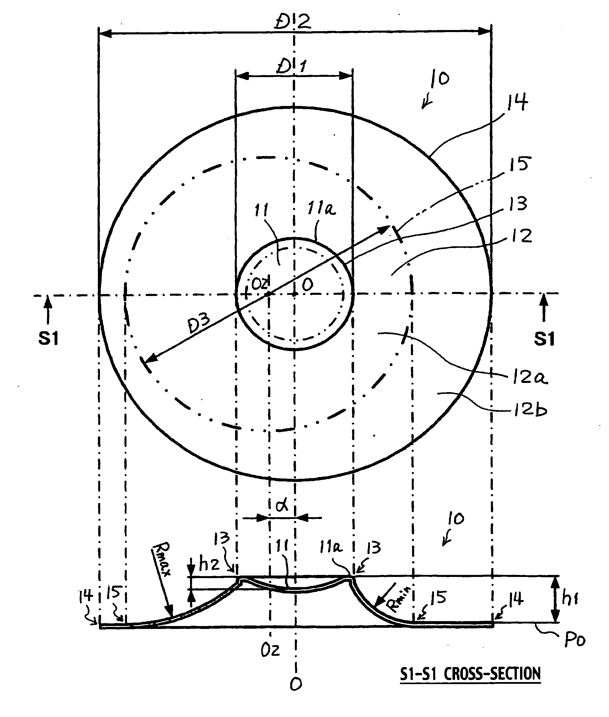
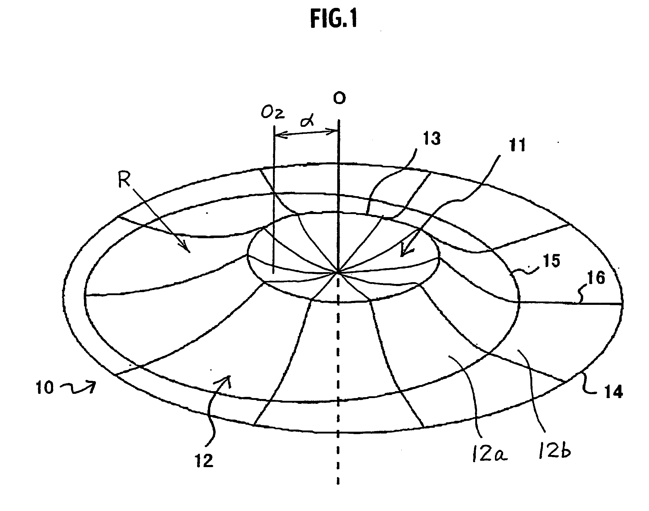
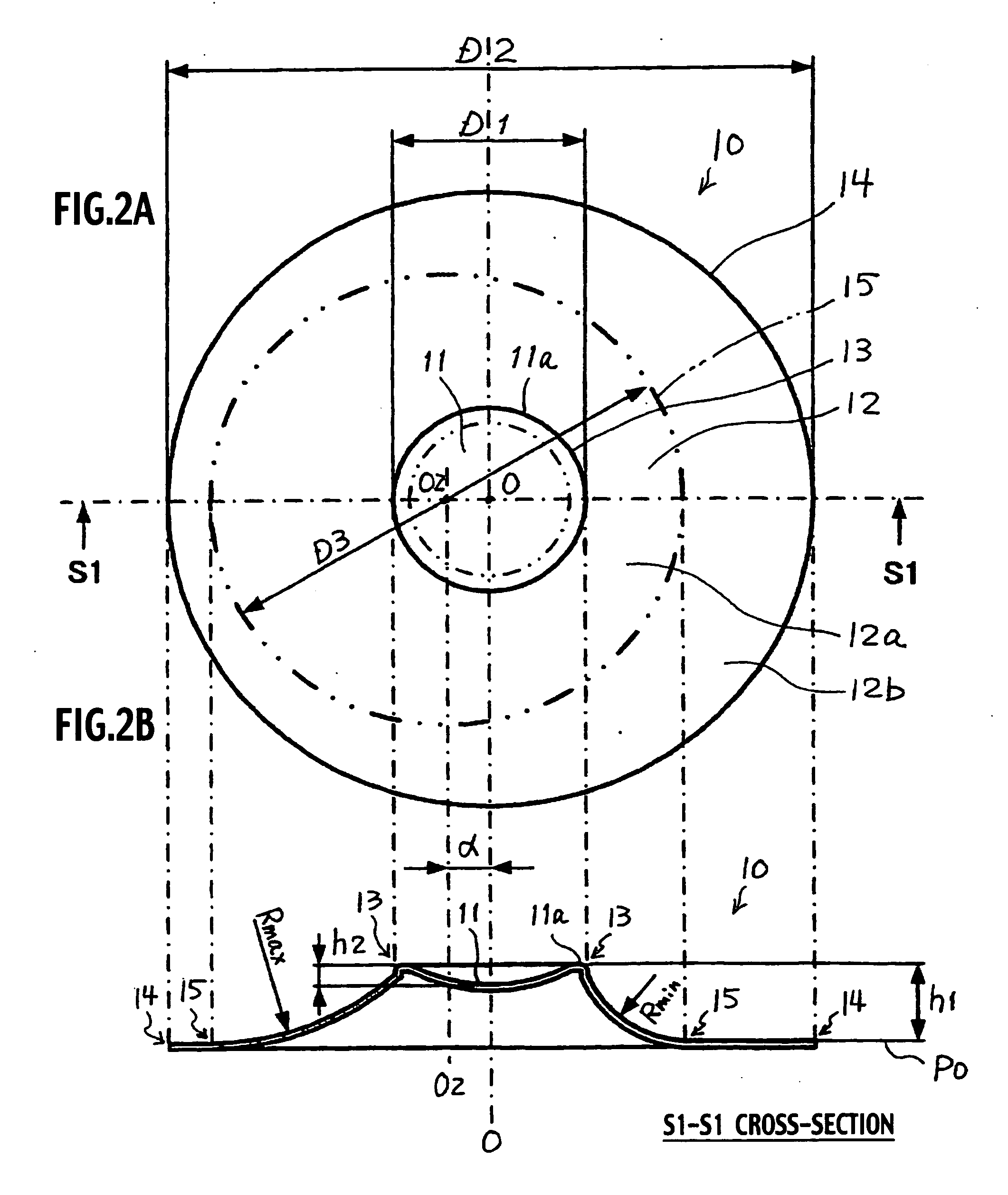
[0090] The shape of a diaphragm according to a first example will be explained using FIGS. 1, 2A and 2B. In FIG. 1, a curvature of the curved surface of a diaphragm 10 is schematically shown with a plurality of solid lines 16 in the radial direction for the sake of easier understanding.

[0091]FIG. 1 is a perspective view showing an external appearance of the diaphragm 10; FIG. 2A is a plan view showing the diaphragm 10; and FIG. 2B is a sectional view taken along the S1-S1 line in FIG. 2A.

[0092] As shown in FIGS. 1, 2A, and 2B, the diaphragm 10 is formed like a nearly disc which includes a center section 11 ranging from a central axis O to an inner diameter section 13 with a diameter D1 [refer to FIG. 2A], and an inclined section 12 ranging from the inner section 13 to an outer diameter section 14 with a diameter D2 [refer to FIG. 2A].

[0093] The material of the diaphragm is not limited to a special one, but a sheet of paper, resin such as polypropylene (PP), metal such as aluminum...

second example

[0155] Then, a diaphragm 100 according to a second example of the present invention will be explained, referring to FIG. 11A and FIG. 11B.

[0156]FIG. 11A and FIG. 11B are schematic plane views, in which a diaphragm 100a having a basic shape of the present example is shown in FIG. 11A and a diaphragm 100 is shown in FIG. 11B, for easier understanding of the shape of the diaphragm 100. Moreover, points at which line segments intersect are shown with black dots for easier understanding in FIG. 11A and FIG. 11B.

[0157] The diaphragm 100 according to the present example, which is shown in FIG. 11B, is a diaphragm configured in such a way which, the diameter D1 which can be arbitrarily set in the inner diameter section 13 according to the first example is set at nearly zero in order to be located on the central axis O of the outer shape, and at the same time, is a top portion TPO, which protrudes to one side with regard to the set reference plane PO defined by including the outer diameter...


PUM

PropertyMeasurementUnit
Diameteraaaaaaaaaa
Flexibilityaaaaaaaaaa
Shapeaaaaaaaaaa

Abstract

A diaphragm in one mode of the present invention comprises an outer shape section having a circle with one diameter, or a shape of a polygon to be inscribed in a circle with the one diameter; an inner shape section protruding in one direction with regard to a plane including the outer shape section, wherein a shape formed by projecting the inner shape section on the plane is rotationally symmetric about the central axis of the circle; and a vibrating face section linking the outer shape section and the inner shape section and having an inclined face inclined to the central axis, wherein any one of cross-sectional shapes of the vibrating face section is rotationally symmetric about an eccentric axis which is eccentric with regard to the central axis, the cross-sectional shapes being defined by a plane intersecting perpendicularly to the central axis. An electroacoustic transducer uses the above diaphragm.

Description

BACKGROUND OF THE INVENTION [0001] 1. Technical Field [0002] The present invention relates to a diaphragm, a spherical-shell diaphragm and an electroacoustic transducer, and a method of manufacturing an electroacoustic transducer. [0003] 2. Description of the Related Art [0004] An electroacoustic transducer, which is provided with a diaphragm, a frame supporting the periphery of the diaphragm, and a driving section with a magnetic circuit which vibrates the diaphragm in a uniaxial direction, and emits a sound, has been generally called a speaker. Such a diaphragm has had quite often a shape of a cone. [0005] Generally, the surface profile of this cone shape is a nearly circular truncated cone, wherein the cone is obtained by cutting off the top portion of a nearly circular cone (right circular cone) with rotational symmetry about a central axis, and has inner and outer peripheries and an inclined portion inclined to the central axis which is in the vibrating direction. [0006] Incide...

Claims


Application Information

Patent Timeline
IPC IPC(8): H04R7/00
CPCY10T29/49005H04R7/122
Inventor INAGAKI, KAZUYUKINAKASO, JIROOMODA, MANABU
Owner JVC KENWOOD CORP A CORP OF JAPAN
Why Eureka
Try Eureka