Liquid filter

Inactive Publication Date: 2006-08-31
MANN HUMMEL GMBH
View PDF16 Cites 37 Cited by
  • Summary
  • Abstract
  • Description
  • Claims
  • Application Information

AI Technical Summary

Benefits of technology

[0011] The liquid filter may be designed as a spin-on filter or as an oil module. The housing may be made of a metallic material or synthetic resin material and the filter element may be made of filter paper or a synthetic material having accordion pleating, coils or alternately sealed channels through which liquid flows from one axial end to the other. This results in an extremely space-saving embodiment of the non-return valve a

Problems solved by technology

However, it is a disadvantage of this arrangement that many different parts are needed for the functioning

Method used


Image

  • Liquid filter
  • Liquid filter
  • Liquid filter

Examples


Embodiment Construction

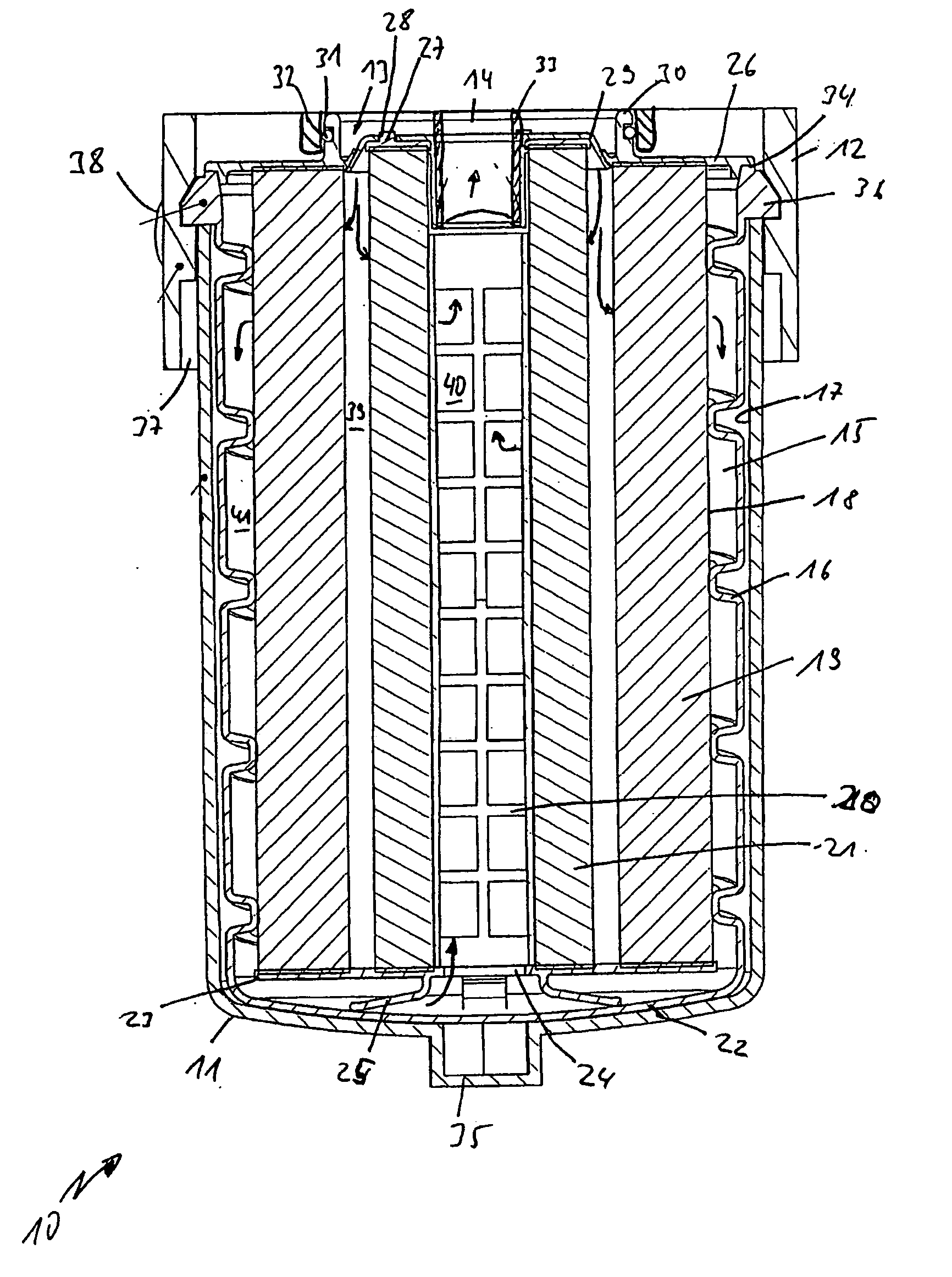
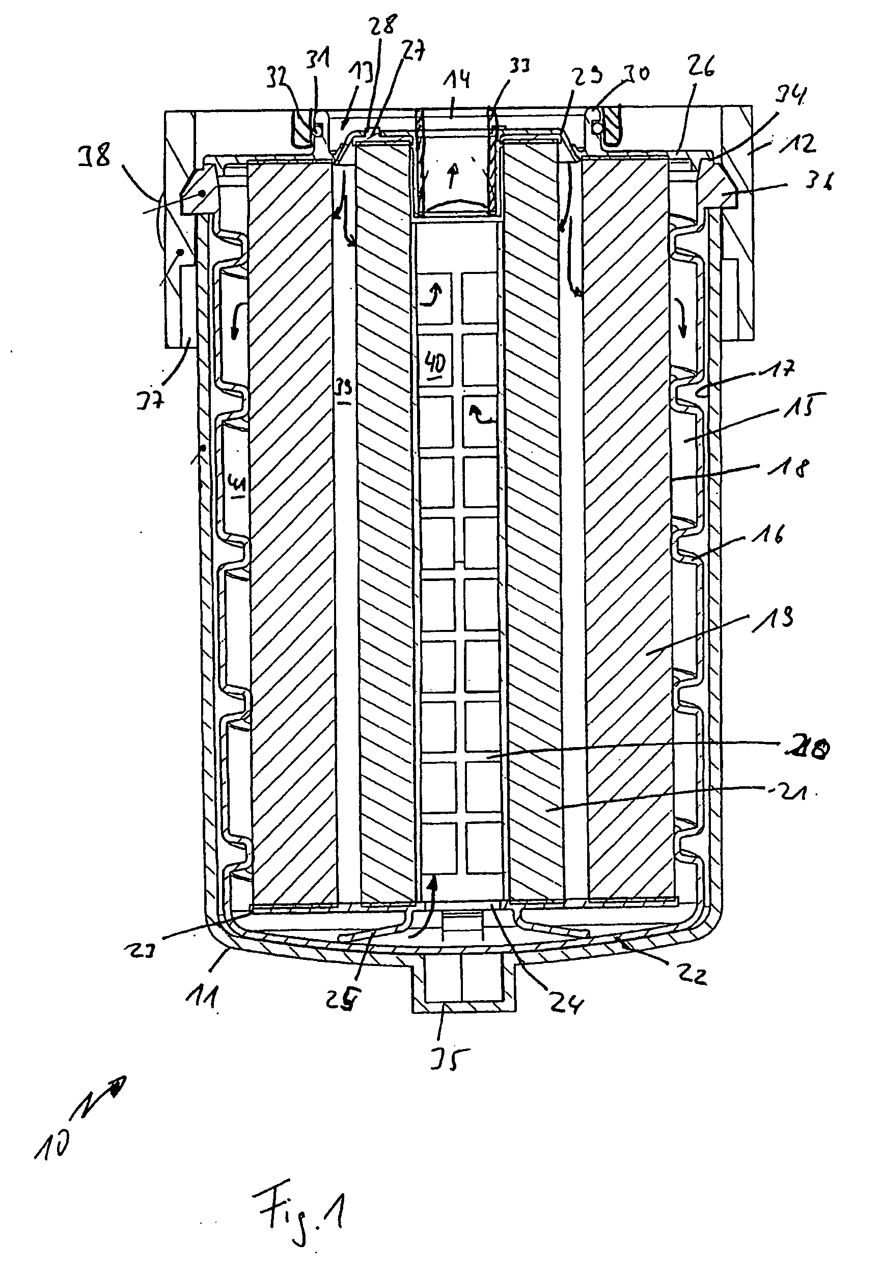
[0034]FIG. 1 is a sectional diagram of a liquid filter system 10, in which a cup-shaped housing 11 is connected by a bayonet connection to a connecting head 12. The connecting head may be a separate connecting flange or it may be formed directly from a component of an internal combustion engine. The filter system may be used, for example, for liquids of any type associated with an internal combustion engine, such as oils, fuels, hydraulic liquids or coolants.

[0035] An inlet 13 and an outlet 14 are provided in the connecting head 12 of the filter system 10. The outlet 14 is arranged concentrically at the center of the connection between the cup-shaped housing 11 and the connecting head 12, and the inlet 13 is arranged concentrically around the outlet 14, likewise being arranged in the interior of the connection between the cup-shaped housing 11 and the connecting head 12.

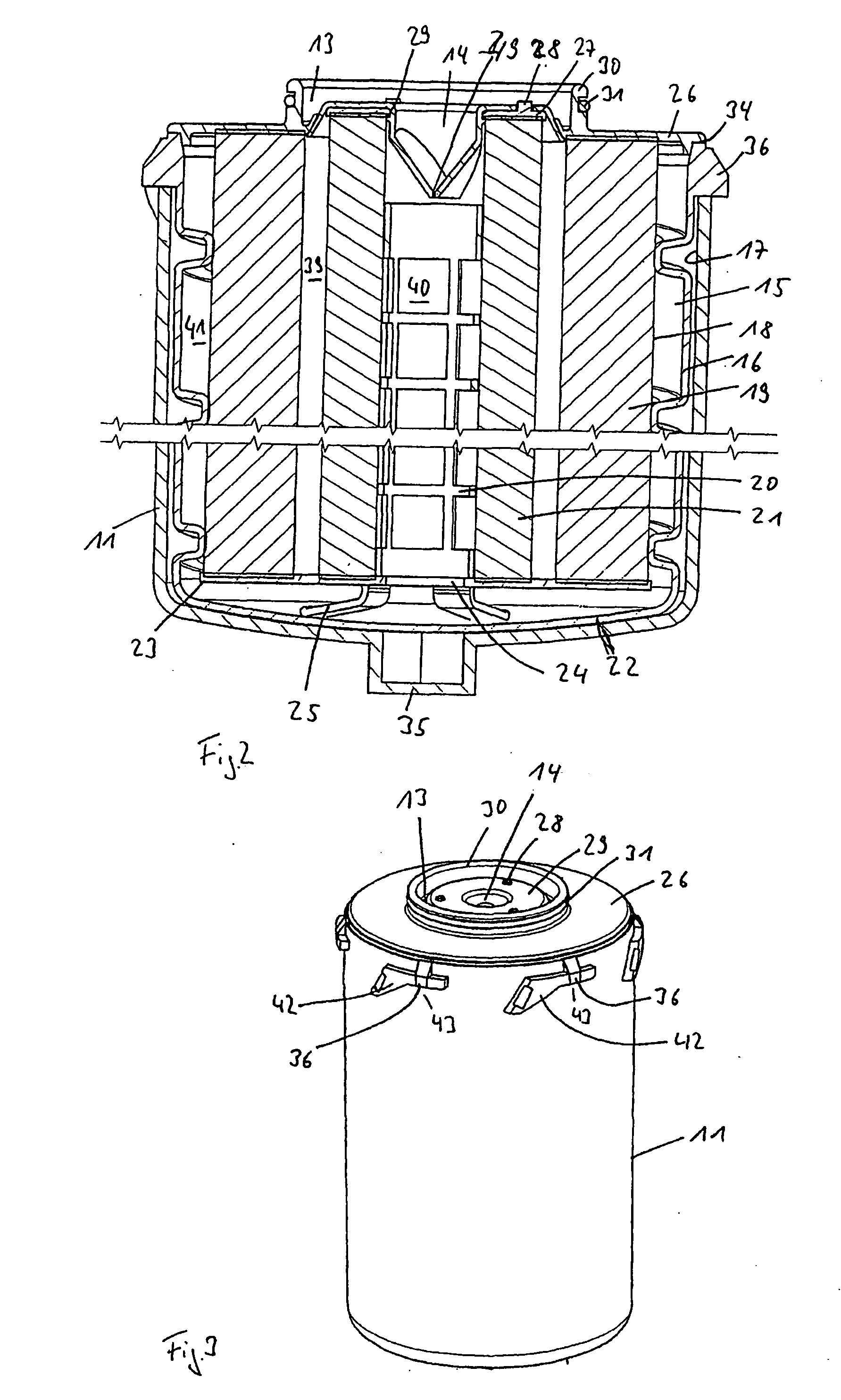
[0036] A filter element 15 is arranged in the cup-shaped housing 11. The illustrated filter element 15 comprises...


PUM

PropertyMeasurementUnit
Elastomericaaaaaaaaaa
Shapeaaaaaaaaaa

Abstract

A liquid filter, especially oil filter for an internal combustion engine, having a cup-shaped housing with a liquid inlet and a liquid outlet, a filter element arranged with a seal between the inlet and outlet, and a one-piece barrier membrane arranged in the area of the opening of the cup-shaped housing such that the liquid inlet and/or the liquid outlet can be closed by the barrier membrane.

Description

BACKGROUND OF THE INVENTION [0001] The present invention relates to a liquid filter according to the preamble of Patent claim 1. [0002] Known liquid filters often include barrier membranes and non-return valves to prevent liquid from flowing back out of the filter when the internal combustion engine is stopped. Such devices also prevent the liquid from flowing out of the filter when the filter is replaced. [0003] Published German Patent application no. DE 41 40 140 describes a screw-on filter for liquids, in particular a lubricating oil filter for an internal combustion engine. Such a filter has a peripheral barrier membrane in the area of the liquid inlet which achieves the sealing function via a peripheral lip which fits sealingly against a cover plate of the replaceable filter. In addition, a non-return valve consisting of a cage, a spring arranged in the cage, and a valve body acted upon by the spring with spring force is mounted centrally in the interior of the filter medium, w...

Claims


Application Information

Patent Timeline
IPC IPC(8): B01D63/00
CPCB01D27/144B01D35/153B01D2201/0415B01D2201/4015B01D2201/4046B01D35/30
Inventor DWORATZEK, KLEMENSBAUDER, RALFMUENKEL, KARLHEINZNGUYEN, DUC CUONG
Owner MANN HUMMEL GMBH
Why Eureka
Try Eureka