
Electric actuation and process for making the same

a technology of electric actuation and process, applied in the direction of dynamo-electric machines, electrical apparatus, magnetic circuits, etc., to achieve the effect of simple and reliable final assembly operation

Inactive Publication Date: 2006-08-31
LUK LAMELLEN & KUPPLUNGSBAU BETEILIGUNGS KG
View PDF9 Cites 13 Cited by
  • Summary
  • Abstract
  • Description
  • Claims
  • Application Information

AI Technical Summary

Benefits of technology

[0006] An object of the present invention is, therefore, to devise an electric drive and a method of the type mentioned at the outset which will allow the electrical components (drive electronics, electric motor) to be installed in the housing in a simple and reliable final assembly operation.

Problems solved by technology

If the electrical components undergo a 100% functional test before being installed in the housing, and the drive still exhibits a fault following the final assembly, then the assumption must be this fault first came into existence in the final-assembly plant.

Method used


Image

  • Electric actuation and process for making the same
  • Electric actuation and process for making the same
  • Electric actuation and process for making the same

Examples


Embodiment Construction

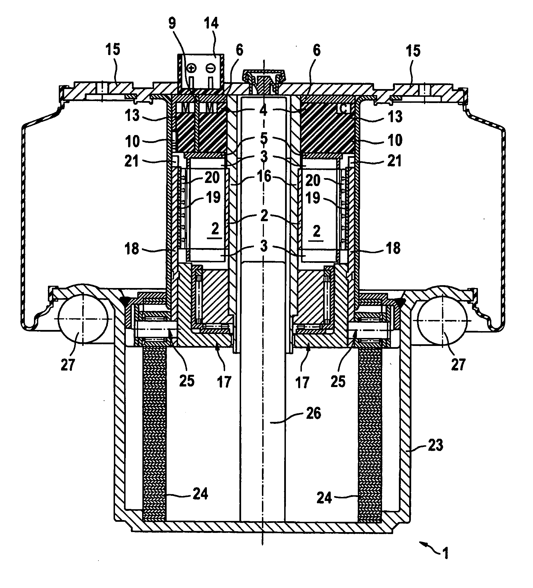
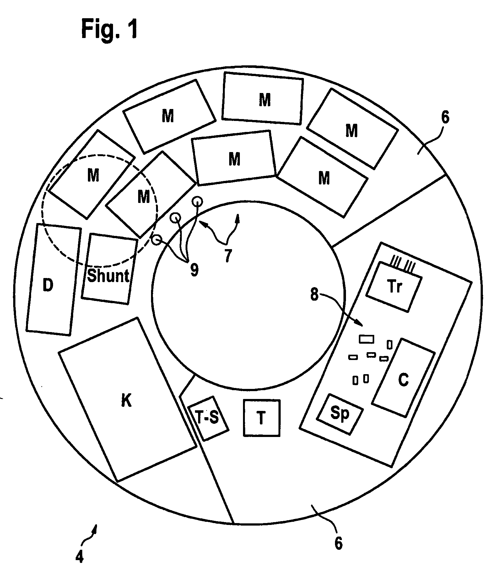
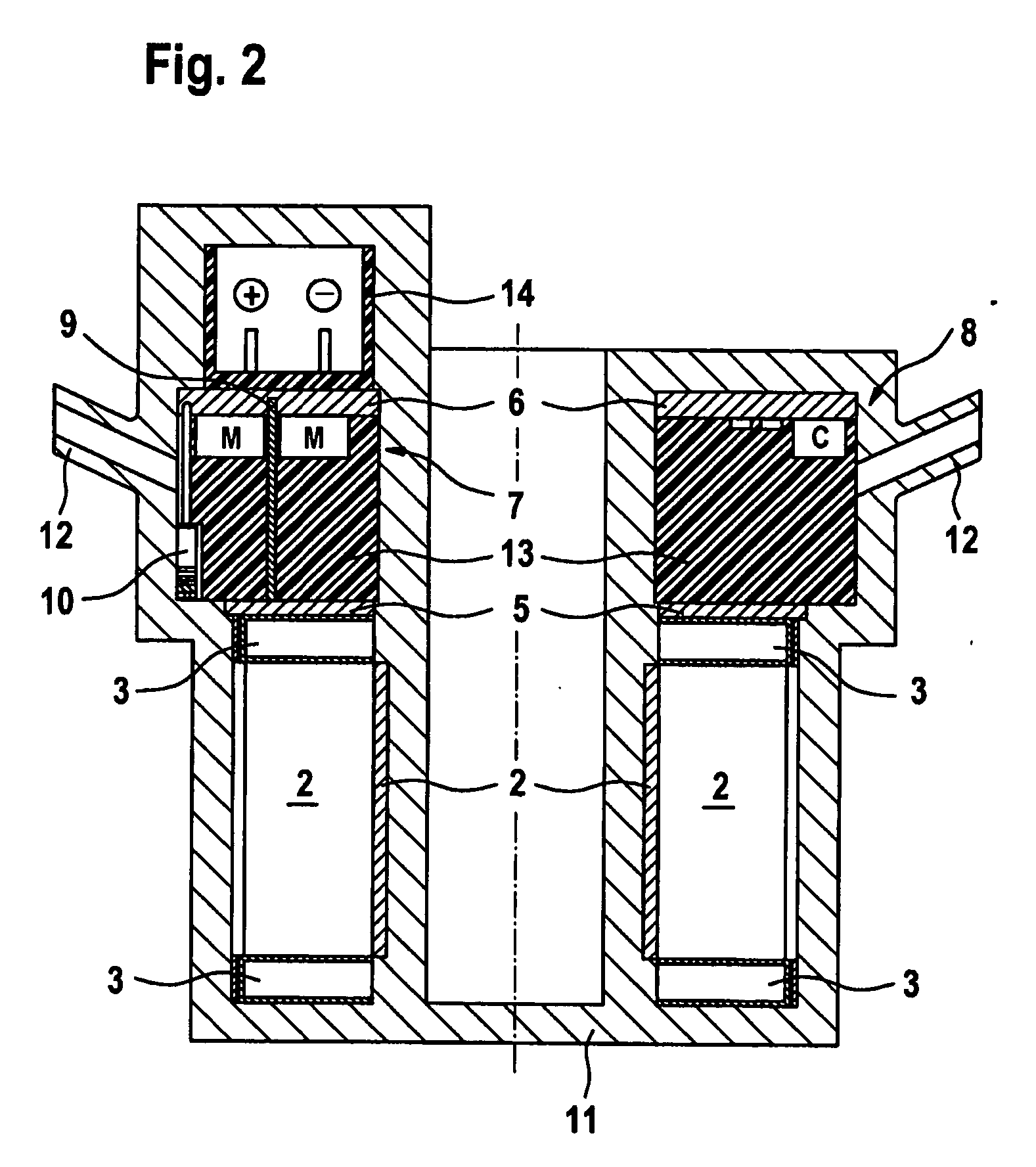
[0037] In a method for manufacturing an electric drive 1, a stator and a rotor are provided for an electric motor. The stator has a laminated core 2 and a winding which has a plurality of winding coils that are offset from one another in a circumferential direction of laminated core 2, the winding coils resting in slots of laminated core 2 and projecting with a plurality of their windings heads 3 past axial ends of laminated core 2. A drive electronics 4 for the winding and an interconnection board 5 are also provided.

[0038] Interconnection board 5 has a plurality of electrical conductors with a plurality of terminal contacts that are connectable to coil ends of the individual winding coils or to connection points of drive electronics 4. In FIG. 1, drive electronics 4 has a circuit substrate 6, which may be formed as a multilayer circuit board or as a plastic-coated lead frame having hybrid ceramics attached thereto. Electrical components for an output stage 7 and a control logic 8...


PUM

PropertyMeasurementUnit
circumferenceaaaaaaaaaa
ride-height levelaaaaaaaaaa
thermal conductivityaaaaaaaaaa

Abstract

In a method for manufacturing an electric drive, an electric motor having a stator, a drive electronics for the winding of the electric motor, and a housing are provided. Before being installed in the housing, the drive electronics and the stator are positioned against each other. Connection points of the drive electronics are electrically connected to the winding of the electric motor. A sealing compound is then brought into contact with the stator and the drive electronics and thereby joins the drive electronics to the stator. The sealing compound is subsequently solidified. Thus, the formed subassembly made up of the stator, the drive electronics and the sealing compound is installed in the interior cavity of the housing.

Description

CROSS REFERENCE TO RELATED APPLICATION [0001] This application claims the benefit of German Patent 10 2005 005 853.1 filed Feb. 8, 2005 and hereby incorporated by reference herein. [0002] The present invention provides a method for manufacturing an electric drive, an electric motor having a stator, a drive electronics for the winding of the electric motor, and a housing being provided, the electric motor and the drive electronics being installed in an interior cavity of the housing, and connection points of the drive electronics being electrically connected to the winding of the electric motor. The present invention also provides an electric drive having an electric motor including a stator, and having a drive electronics for the winding of the electric motor, the electric motor and the drive electronics being placed in the interior cavity of a housing. BACKGROUND OF THE INVENTION [0003] An electric drive of this kind used for a cordless screwdriver and a method for manufacturing th...

Claims


Application Information

Patent Timeline
Patent Type & Authority Applications(United States)
IPC IPC(8): H02K1/04H02K5/10
CPCH02K7/06H02K11/0073H02K15/0056Y10T29/49009H02K15/14H02K15/16H02K15/12H02K11/33
Inventor HILL, WOLFGANG
Owner LUK LAMELLEN & KUPPLUNGSBAU BETEILIGUNGS KG
Learn More