Data strobe synchronization for DRAM devices

Active Publication Date: 2006-08-31
POLARIS INNOVATIONS
View PDF3 Cites 39 Cited by
  • Summary
  • Abstract
  • Description
  • Claims
  • Application Information

AI Technical Summary

Benefits of technology

[0009] One embodiment provides a method for adjusting the timing of an internal signal within an integrated circuit. The method generally includes determining a phase difference between first and second externally supplied timing signals, generating a multi-bit control signal based upon the determined phase difference, and adjusting the timing of the internal signal based upon the multi-bit control signal.
[0010] Another embodiment provides a method for adjusting the timing of one or more signals used by a memory device. The method generally includes determining a phase difference between an externally supplied clock signal (CLK) and an externally supplied data strobe signal (DQS), generating a multi-bit control signal based upon the determined phase difference, and adjusting the timing of the one or more signals based upon the multi-bit control signal.
[0011] Another embodiment provides an apparatus for adjusting internal timing of an integrated circuit based on first and second externally supplied timing signals. The apparatus generally includes at least one phase detection circuit configured to detect a difference in phase between the first and second externally supplied timing signals and generate at least one de

Problems solved by technology

In many memory designs there is often more than one timing signal and generally these timing signals may be skewed.
The memory's internal timing must be able to operate over this entire range of CLK / DQS timing, which is becoming more difficult as clock speed increase.
As memory clock speeds increase, it becomes more difficult to compensate for these timing differences and internal signals derived from these clock and data strobe signals may need to be closer aligned to the clock to prevent errors from occurring.
However, in conventional designs, no attempt has been made to detect this phase difference.

Method used


Image

  • Data strobe synchronization for DRAM devices
  • Data strobe synchronization for DRAM devices
  • Data strobe synchronization for DRAM devices

Examples


Embodiment Construction

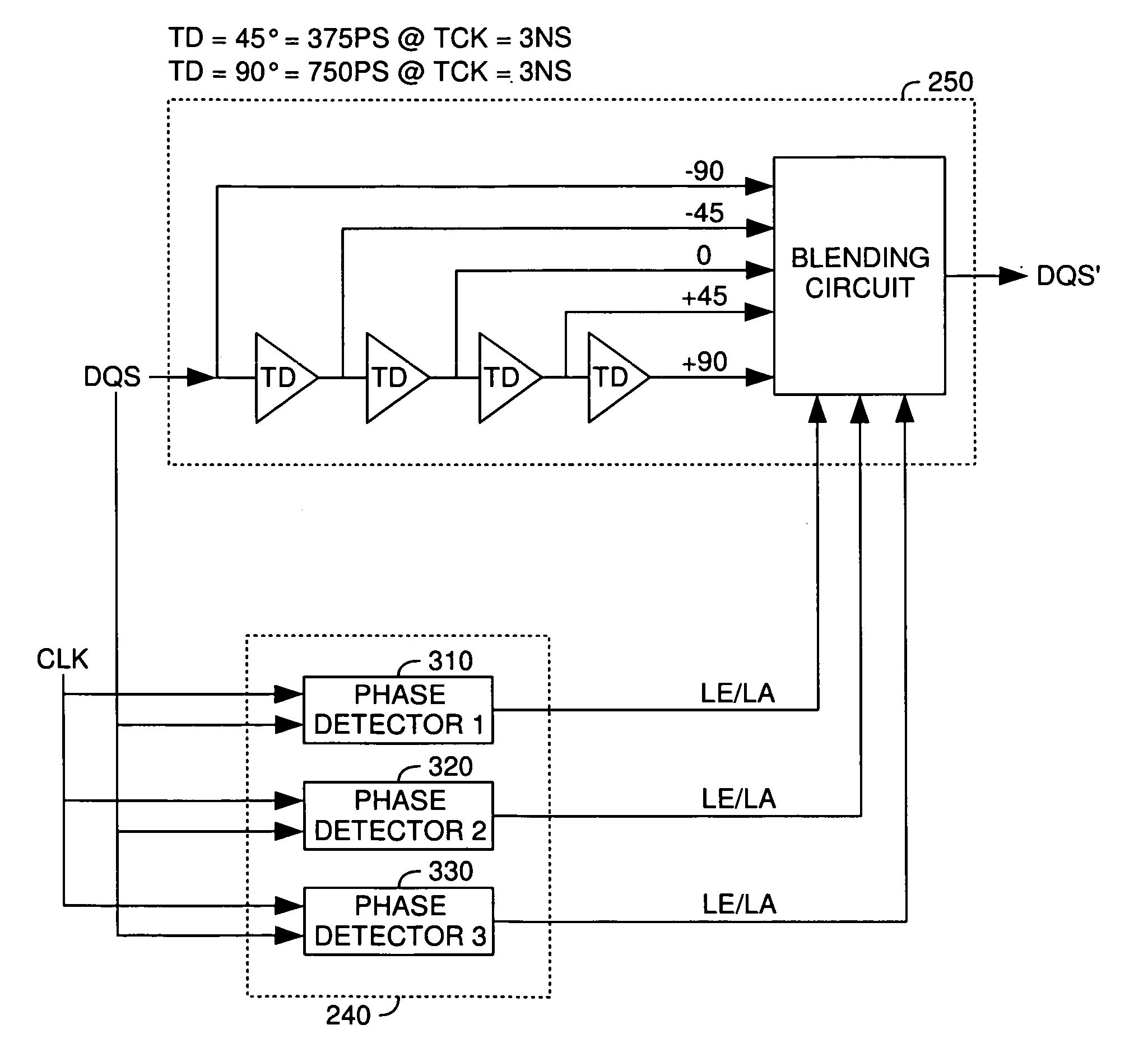
[0020] Embodiments of the present invention generally determine, at a device (e.g., a DRAM device), a phase difference between two signals such as a clock signal (CLK) and a data strobe signal (DQS), and adjusts some parameters of timing based on the measured difference. In some embodiments, the adjustment is made to the data strobe signal itself (DQS). In other embodiments, the adjustment is made to other internal memory signals that are, perhaps, utilized in circuits controlled by the DQS signal (e.g., these signals are within the DQS domain).

[0021] To facilitate understanding, embodiments of the present invention will be described with reference to memory devices, specifically DRAM devices, as specific, but not limiting application examples. However, those skilled in the art will recognize that the same principles described herein may be applied to adjust the timing of various control signals in various other types of integrated circuits, based on a detected phase difference bet...


PUM


Abstract

Methods and apparatus that determine, at a device (e.g., a DRAM device), a phase difference between two externally supplied timing signals such as a clock signal (CLK) and a data strobe signal (DQS) are provided. Adjustments may be made to timing of one of the signals itself or other internal memory signals that are, perhaps, utilized in circuits controlled by the DQS signal.

Description

BACKGROUND OF THE INVENTION [0001] 1. Field of the Invention [0002] The invention generally relates to memory devices and, more particularly, to detecting the phase difference between a clock signal and a data strobe signal. [0003] 2. Description of the Related Art [0004] In many memory designs there is often more than one timing signal and generally these timing signals may be skewed. In general, skew refers to the difference in timing between two timing signals, e.g., the time from the leading edge of the first timing signal to the leading edge of the second timing signal. In some designs, one timing signal may be allowed to be skewed to another by a predetermined allowance. For example, in current double data rate DDR dynamic random access memory (DRAM) designs, the phase relationship of a data strobe signal (DQS) and a clock signal (CLK) may be skewed by up to + / −25%. In some memory designs, certain logic within the memory may be timed to the CLK signal, or within the CLK domain...

Claims


Application Information

Patent Timeline
IPC IPC(8): G11C8/00
CPCG11C7/22G11C7/222G11C11/401G11C11/4076G11C29/02G11C29/022G11C29/028G11C29/50012H04W48/20H04W84/12H04W88/08
Inventor SCHNELL, JOSEF
Owner POLARIS INNOVATIONS
Why Eureka
Try Eureka