Tunable fiber laser light source

a fiber laser and light source technology, applied in the direction of laser details, basic electric elements, optical resonator shape and construction, etc., can solve the problems of low light density, inability to detect light signals, low light density of light source with respect to wavelength, etc., to achieve high deflection velocity, extend optical path length, and keep band width narrow

Active Publication Date: 2006-08-31
SANTEC
View PDF6 Cites 121 Cited by
  • Summary
  • Abstract
  • Description
  • Claims
  • Application Information

AI Technical Summary

Benefits of technology

[0013] According to the present invention having such characteristics, an optical fiber loop is used as an optical path of laser oscillation to extend an optical path length and change an oscillation wavelength by means of a tunable filter. In the tunable filter, an optical beam deflector deflects light and inputs the light to a diffraction grating. The diffraction grating, used as a filter which varies in wavelength according to an incident angle, makes light reflective in the same direction as incident light. Consequently the tunable filter constitutes a part of the optical path, so that the oscillation wavelength can be determined in response to a selected wavelength of the filter. Then, continuous change of the incident angle to the diffraction grating results in continuous change of the selected wavelength of the tunable filter, thereby enabling the oscillation wavelength to change. Sufficiently high deflection velocity of the optical beam deflector permits wavelength scanning at high speed. A plurality of times of inputting light from the same direction at the diffraction grating can provide effects to keep band width narrow even when scanning wavelength at high speed and to obtain narrow band laser light.

Problems solved by technology

In such spectral analysis, however, the intensity and density of the light from the light source with respect to the wavelength is low, and those of light which is used in spectral analysis is also low.
Consequently, the light source has a drawback such that even if Fourier transformation is performed, a light signal cannot be detected due to noise, and it is difficult to carry out the analysis.
Therefore, when the wavelength of the tunable filter is simply changed, the output becomes unstable between the longitudinal modes.
Therefore, in order to vary the wavelength continuously in a single mode and to, moreover, make the output stable, the length of the external cavity has to be controlled finely by using such devices as a piezo-element and a complicated control is necessary.
Consequently, the method has a drawback that it is difficult to change the wavelength at high speed.
However, a tunable laser light source capable of performing the high-speed scanning in such a manner as to follow an image display frame rate has not been available so far.
In the conventional filter techniques, however, it is difficult to obtain both high-speed wavelength sweep and a high Q value at the same time.
For example, a tunable filter using an acoustooptic effect has a drawback such that, due to an insufficient suppression ratio at wavelengths other than the transmission wavelength, stable oscillation cannot be performed.
In the case of forming a Fabry-Perot etalon by using a piezo-element as a bandpass filter, the wavelength sweep speed is as low as a few Hz or less and the case has a problem of hysteresis.
In the case of using a grating for the bandpass filter, there are drawbacks such that adjustment of the optical axis is difficult and the cost is high.

Method used


Image

  • Tunable fiber laser light source
  • Tunable fiber laser light source
  • Tunable fiber laser light source

Examples


first embodiment

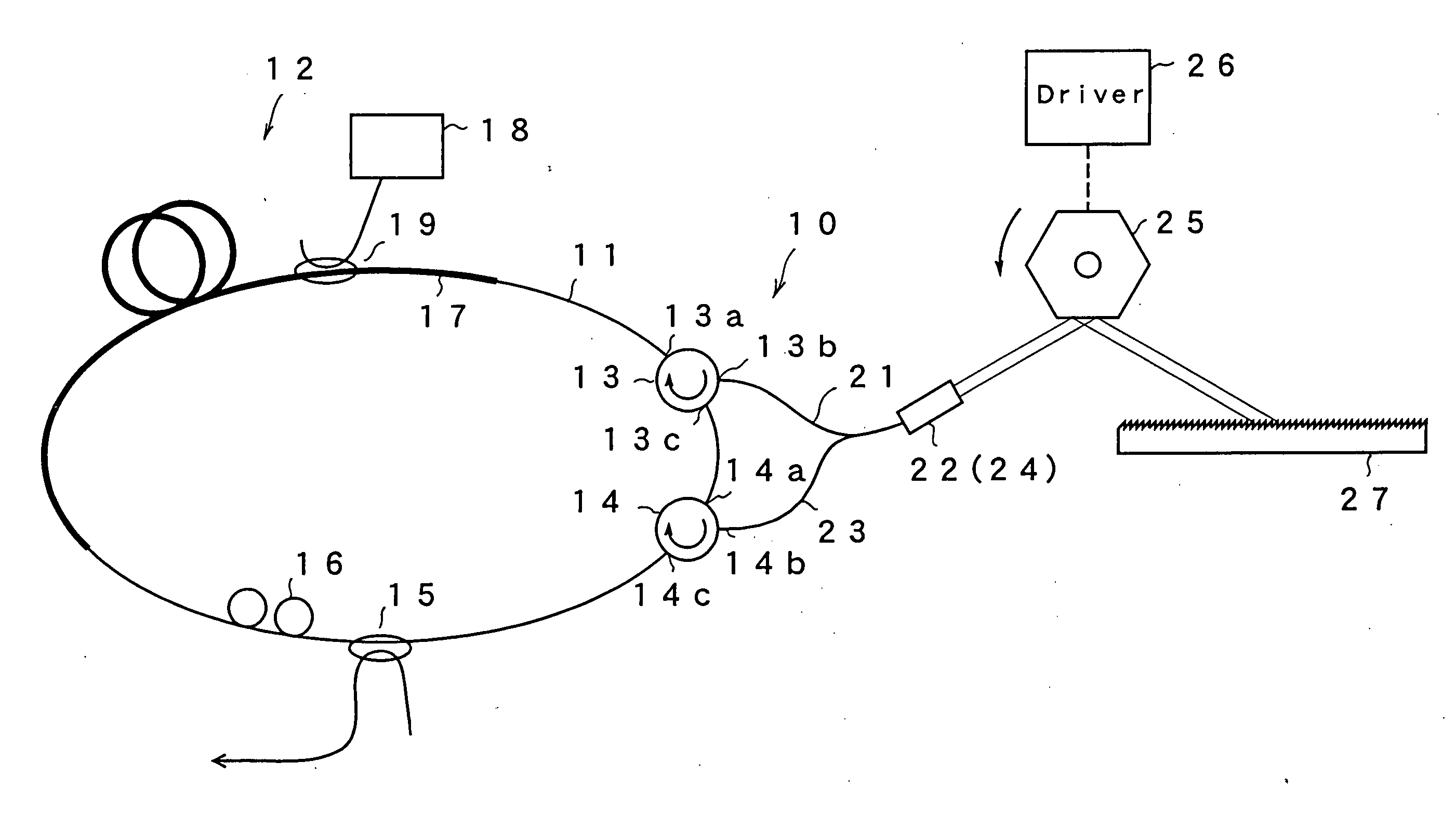
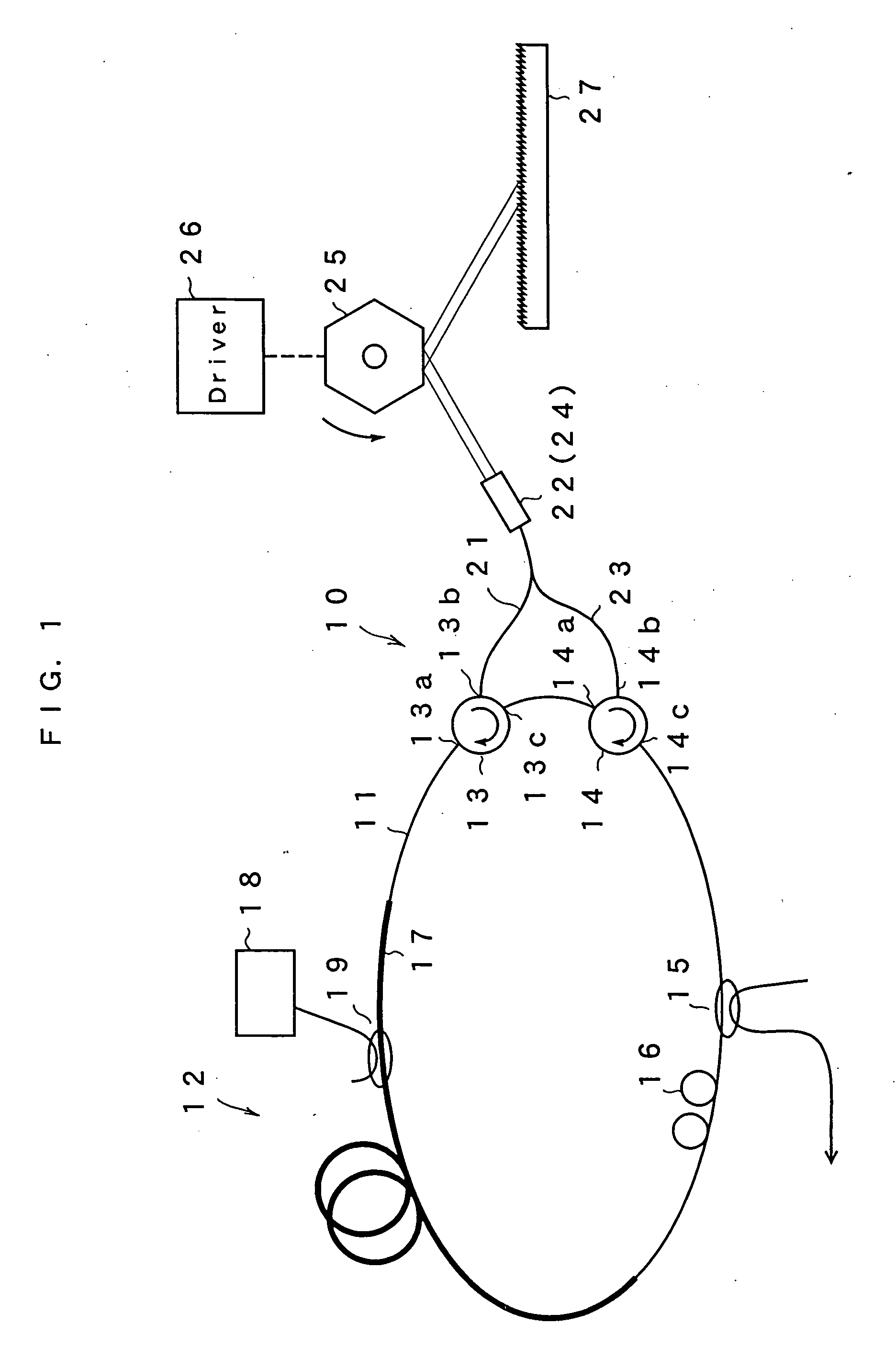
[0032]FIG. 1 is a schematic view showing the configuration of a tunable fiber laser light source according to a first embodiment of the present invention. A tunable fiber laser light source 10 of this embodiment forms a loop by including an optical fiber 11. In a part of the loop, a gain medium 12, optical circulators 13 and 14, an optical coupler 15 and a polarization controller 16 are provided. The gain medium 12 has an erbium doped fiber 17 provided in a part of the optical fiber loop and doped with erbium ions (Er3+), a semiconductor laser 18 for exciting the fiber for emitting pump light to the erbium doped fiber 17, and a WDM coupler 19. The wavelength bandwidth of the gain can be adjusted by selecting a material with which the erbium doped fiber is doped. The optical fiber loop has a length of, for example, 1 to 50 m. The semiconductor laser 18 for exciting has a wavelength of, for example, 1480 nm or 980 nm and amplifies light passing through the erbium doped fiber 17. The o...

second embodiment

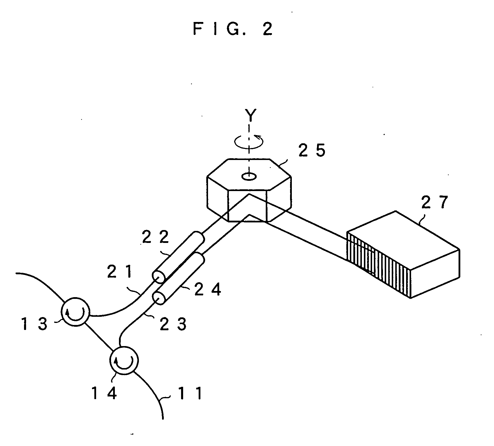
[0042] Next, a second embodiment of the present invention will be described. There is no difference between the present embodiment and the first embodiment in terms of the optical fiber loop, and the structure from the circulator 13 to the optical fibers 21 and 22, and collimate lenses 23 and 24. In the present embodiment, an optical beam diameters of the light emitted from the collimate lenses 23 and 24 are expended as shown in FIG. 5. When a beam diameter of an optical beam from the collimate lenses 23 and 24 are W1, the optical beam diameters are enlarged to W2 by a beam expander 31 having a prism shape as shown in FIG. 5. The light reflected in the polygon mirror 25, the optical beam diameters of which are further enlarged to W3 by a beam expander 32, is added to the diffraction grating 27. The optical beam diameters of the incident light with respect to the diffraction grating 27 can be thus enlarged.

[0043]FIG. 6 is an enlarged view of the beam expander 32 and the diffraction ...

third embodiment

[0050]FIG. 9 is a view showing a tunable fiber laser light source according to a third embodiment of the present invention. This embodiment uses a four-port type optical circulator as a light branch incident section in place of two three-port type optical circulators. The four-port type optical circulator 41 has terminals 41a and 41d connected to the optical fiber loop. Light inputted from the terminal 41a is emitted to a terminal 41b of the optical circulator. The light inputted from the terminal 41b is emitted from a terminal 41c. The light inputted from the terminal 41c is emitted from the terminal 41d. The light inputted from the terminal 41d is emitted from the terminal 41a. Consequently, this embodiment can use the four-port type optical circulator 41 as the light branch incident section in place of two optical circulators 13 and 14 of the first embodiment. Other construction is the same as in the first embodiment. In this case, the rotation of the polygon mirror 25 along the ...


PUM


Abstract

An optical fiber loop has a gain medium having a gain at an oscillation wavelength and optical circulators 13 and 14. Collimate lenses 22 and 24 enlarge light bean taken from the optical circulators 13 and 14. A polygon mirror 25 is provided on the light axis, and is rotated. A diffraction grating 27 is provided at the receiving position of the light reflected by the polygon mirror 25, and is of a Littrow configuration which reflects the light in the same direction as the incident light. A selected wavelength changes according to an incident angle to the diffraction grating 27, resulting in increase of selectivity owing to twice incident, thereby permitting to change an oscillation wavelength with narrow band even when changing the selected wavelength by rotating the polygon mirror 25 at high speed.

Description

BACKGROUND OF THE INVENTION [0001] 1. Field of the Invention [0002] The present invention relates to a tunable fiber laser light source, which generates monochromatic light to periodically scan an emission wavelength thereof. [0003] 2. Discussion of the Related Art [0004] Hitherto, as a light source of an analyzer for analyzing an object to be measured by irradiating the object with light, a light source of a wide bandwidth is used. In spectral analysis, there is widely used a method of projecting light of a wide bandwidth to an object to be measured, spatially decomposing reflection light or transmission light of the projected light to wavelength components by a grating or the like, Fourier-analyzing the frequency components by an interferometer, and making an analysis. As a light source used in such a method, for example, a white light source, an ASE light source using an erbium doped fiber (EDF), or the like is used. In such spectral analysis, however, the intensity and density o...

Claims


Application Information

Patent Timeline
Patent Type & Authority Applications(United States)
IPC IPC(8): H01S3/30H01S3/08
CPCH01S3/067H01S3/06791H01S3/083H01S3/105H01S3/1055H01S3/1608H01S5/141H01S5/142
Inventor CHONG, CHANGHOMOROSAWA, ATSUSHISAKAI, TOORU
Owner SANTEC
Why Eureka
Try Eureka